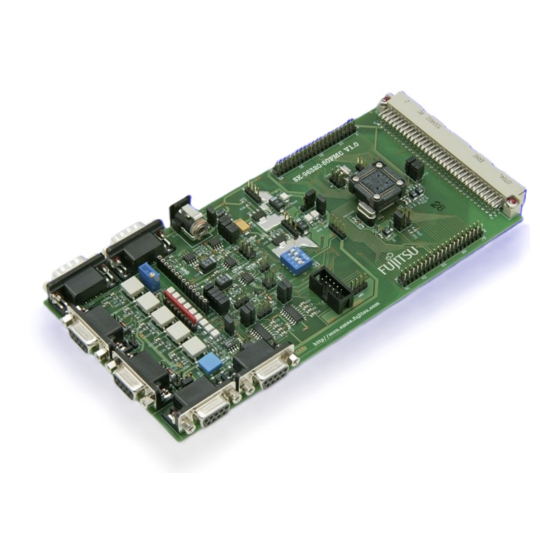
Fujitsu SK-96320-80PMC User Manual - Page 19
Browse online or download pdf User Manual for Motherboard Fujitsu SK-96320-80PMC. Fujitsu SK-96320-80PMC 34 pages.
Also for Fujitsu SK-96320-80PMC: User Manual (34 pages), User Manual (34 pages)

3.10 CAN"B" (JP: 27, 28)
One high-speed CAN-transceiver can be connected to the microcontroller's CAN interface.
JP27, JP28 connects a CAN-port to the CAN-transceiver (U8, X11).
If the CAN interface is not used then the jumpers should be left open.
JP33
selects power supply of the CAN B transceiver (5V / 3V3)
Jumper
JP27 (CAN"A"TX)
JP28 (CAN"A"RX)
JP33 (VCC CAN B)
3.11 I²C Pull-Up (JP: 46, 47)
Two 10k Ohm resistors can be connected to the SDA0 and SCL0 lines.
Jumper
JP46 (SDA0)
JP47 (SCL0)
3.12 C-Pin Capacitor
For normal operation the C-pin must be connected to two capacitors. For test purposes you
can disconnect these two capacitors.
Jumper
JP40 (C-Pin)
© Fujitsu Microelectronics Europe GmbH
SK-96320-80PMC User Guide
Chapter 3 Jumpers and Switches
Setting
Description
closed
TX2 of MCU is connected to CAN"B"
closed
RX2 of MCU is connected to CAN"B"
1-2
CAN B VCC is set to 5V
2-3
CAN B VCC is set to 3V3
Setting
Description
closed
SDA0 is pulled up to VCC
closed
SCL0 is pulled up to VCC
Setting
Description
C-Pin is connected to capacitors for normal
closed
operation
C-Pin is left open (not recommended for normal
open
operation)
- 19 -
FMEMCU-UG-960010-11
