Recommended Spare Parts Replacement
6. Slide the drive shaft (complete with operator) out of the actuator.
7. Reach into the housing and remove the worm gear, thrust bearing(s) and bearing races. The Size 6
actuator has one thrust bearing and two bearing races; the Size 12 has two bearings and four
bearing races.
8. Remove the gear sector seals from the top cover and adaptor.
9. Remove the drive shaft seal from the housing.
10. Scrape the gasket material from the top cover and actuator housing.
11. Grease the new seals and press them into the top cover and adaptor.
12. Push a new drive shaft seal into the housing.
13. Size 6 Actuators - Slide the drive shaft into the housing and thru these components in the following
order: bearing race, bearing, bearing race, worm gear, and then into the bearing in the housing.
Size 12 Actuators - Slide the drive shaft into the housing and thru these components in the
following order: bearing race, bearing, bearing race, worm gear, bearing race, bearing, bearing
race, and then into the bearing in the housing.
14. Turn the drive shaft and worm gear until the holes in them line up with the pipe plug hole in the
housing.
15. Reaching in thru the pipe plug hole, insert the pin to connect the drive shaft and worm gear.
16. Screw the pipe plug into the hole in the housing.
17. Place the gear sector on the valve shaft in the same position noted before it was removed.
18. Apply a liberal amount of grease to the gear sector, bearings and worm gear.
19. Set a new cover gasket on the housing, then install and fasten the top cover on the housing; make
sure the scribe marks line up (non-submerged units only).
20. Install the actuator on the valve as described in the ACTUATOR INSTALLATION Section of this
Instruction.
Size 16 Actuators
1. Remove the actuator from the valve as described in the ACTUATOR REMOVAL Section of this
Instruction.
2. Scribe corresponding lines on the actuator cover and housing, then remove the cover screws and
cover from the top of the actuator (non-submerged units).
3. Note the position of the gear sector in the housing, then lift the gear sector out.
4. Mark one tooth on the rack with a center punch, then mark two adjacent teeth on the gear so the
rack and gear can be re-installed in the correct position.
5. Remove the four screws that hold the drive shaft housing assembly to the actuator housing.
6. Turn the operator clockwise to remove the drive shaft housing assembly from the actuator housing.
7. Lift the gear sector and rack from the housing.
8. Drive the pin out that holds the rack guide in place, then remove the rack guide and pin from the
housing.
August 2012
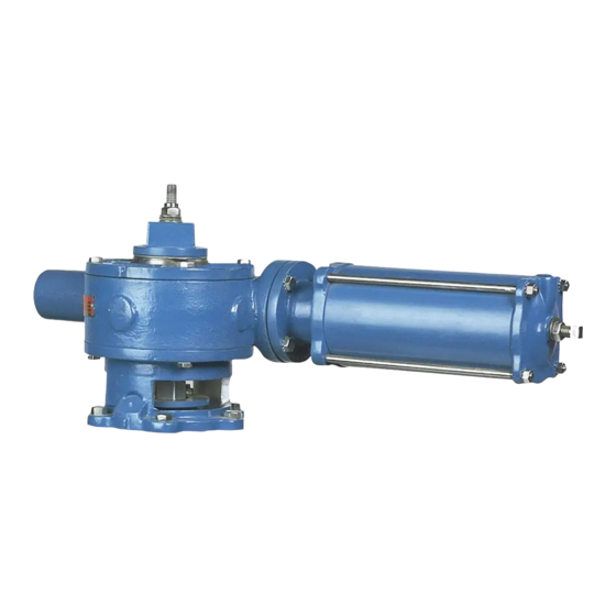
Manual G-Series Actuators on PEC Eccentric Valves
(Continued)
Page 11
DeZURIK
D10063