DeZURIK
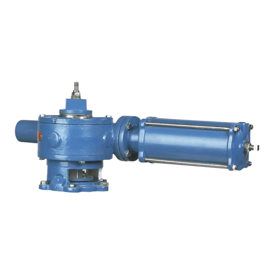
Manual G-Series Actuators on PEC Eccentric Valves
Recommended Spare Parts Replacement
9. Remove the gear sector seals from the top cover and adaptor.
10. Scrape the gasket material from the top cover, actuator housing and drive shaft housing.
11. Rebuild the drive shaft housing assembly as follows:
a. Remove the set screw inside the housing and turn the threaded collar out. The bearing
and two bearing faces will also come out.
b. Remove the pin securing the operator to the drive shaft and slide the operator off the
shaft.
c. Push the housing off the operator end of the drive shaft. The remaining bearing and two
races will come out at this time.
d. Pull the seal out of the drive shaft housing.
e. Lightly grease the new seal and slide it into the drive shaft housing.
f.
Sandwich the bearing between the two races and slide them down the operator end of
the drive shaft until they sit on the sleeve.
g. Apply a liberal amount of grease to the bearing and races.
h. Carefully push the operator end of the drive shaft thru the seal from inside the housing.
i.
Slide the operator onto the shaft, line up the holes in the operator and shaft, then install
the pin.
j.
Sandwich the bearing between the two races and slide them against the sleeve inside
the housing.
k. Apply a liberal amount of grease to the bearings.
l.
Screw the threaded collar into place and secure with the set screw.
12. Grease the new seals and press them into the top cover and adaptor.
13. Pin the rack guide in position in the housing.
14. Place the gear sector and rack in the housing, carefully aligning the teeth marked during
disassembly.
15. Place a new gasket on the drive shaft housing, then push the drive shaft housing assembly into
the actuator housing.
16. Turn the operator counterclockwise to screw the drive shaft into the rack until the drive shaft
housing is tight against the actuator housing.
17. Fasten the drive shaft housing to the actuator housing with four screws.
18. Apply a liberal amount of grease to the gear sector and rack.
Set a new cover gasket on the housing, then install and fasten the top cover on the housing;
19.
make sure the scribe marks line up (non-submerged units only).
Install the actuator on the valve as described in the ACTUATOR INSTALLATION Section of this
20.
Instruction.
D10063
(Continued)
Page 12
August 2012