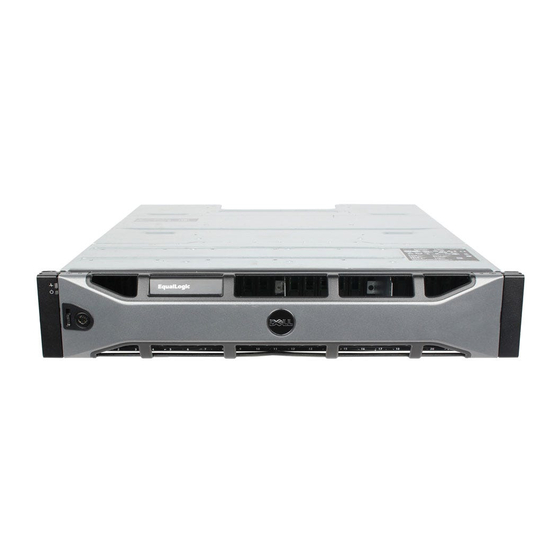
Dell EqualLogic PS Series Hardware Owner's Manual - Page 7
Browse online or download pdf Hardware Owner's Manual for Storage Dell EqualLogic PS Series. Dell EqualLogic PS Series 50 pages. Storage arrays
Also for Dell EqualLogic PS Series: Setting Up (2 pages), Hardware Owner's Manual (48 pages), Hardware Maintenance (46 pages)

1 Basic Storage Array Information
This chapter includes information about the location and basic operation of the replaceable
components in a storage array, tools and equipment you will need, protecting hardware from
electrostatic discharge, and power on and off operations.
About the PS6610 Array
The PS6610 array is a PS6x10 10GbE class EqualLogic PS Series array that continues the focus by
Dell on industry-standard features and capabilities for the midrange iSCSI SAN market. PS Series
Storage Arrays version 8.0 introduces the PS6610.
PS6610 Features
The PS6610 array is a 5U chassis that can be configured with either 42 or 84 drives. Both 2.5-inch
and 3.5-inch drives are supported in either configuration. Features of the PS6610 include:
• Two hot-swappable Type 18 control modules, which contain increased memory (16GB per
controller) and a more powerful processor than previous generation controllers.
• 5U SAS Drive Enclosure
• Ethernet ports:
– Two pairs of 10Gb/s dual-media interfaces (10GBASE-T/SFP+)
– Ability to fall back to 1 GB/s interface (10GBASE-T ports only)
• Support for ReadyRails™ II
Front-Panel Features and Indicators
The main features of the front panel are shown in
right sides of each drawer on the PS6610 each contain an anti-tamper lock (see
handle for opening the drawer, and a sideplane status indicator (see
operation and activity of each sideplane. As you face the front of the chassis, an Enclosure Status
Indicator is located on the left edge that provides status information for the entire array (see
4).
•
Table 2
describes the sideplane status indicators located on the drawers.
•
Table 3
describes the enclosure indicator.
Figure 1
and identified in
Figure
Table
1. The left and
Figure
2), a recessed
3) that monitors the
Figure
1
