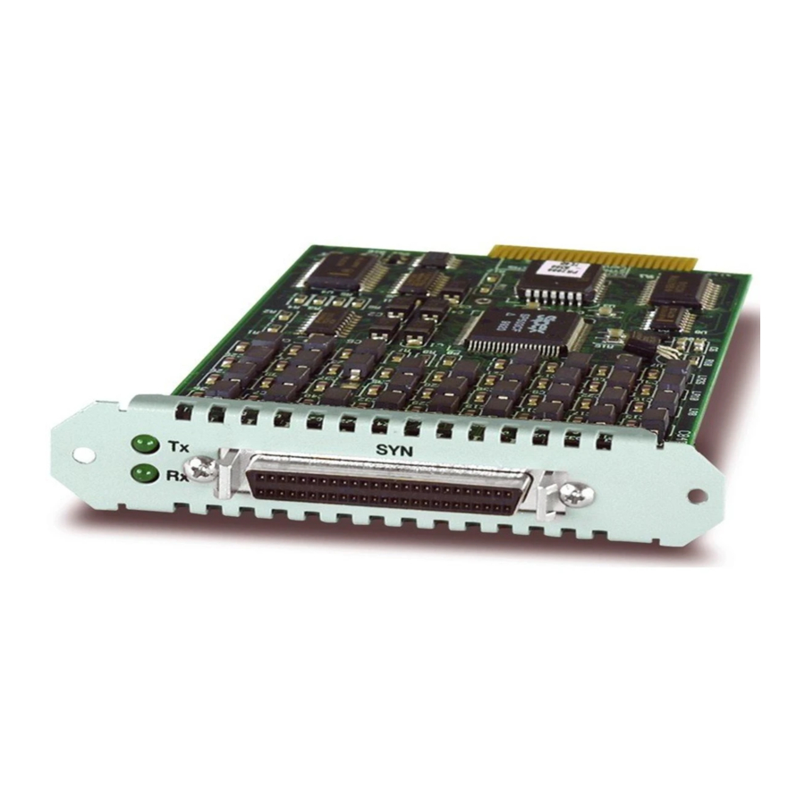
Allied Telesis AT-AR027 VoIP-FXS Installation Manual - Page 5
Browse online or download pdf Installation Manual for Network Card Allied Telesis AT-AR027 VoIP-FXS. Allied Telesis AT-AR027 VoIP-FXS 13 pages. Port interface card
Also for Allied Telesis AT-AR027 VoIP-FXS: Installation Manual (13 pages), Datasheet (1 pages), Datasheet (1 pages), Quick Install Manual (10 pages), Installation And Safety Manual (8 pages)

4
Package Contents
The following items are included with each Port Interface Card (PIC). Contact your
authorised Allied Telesis distributor or reseller if any items are damaged or missing.
two spring-loaded retaining thumbscrews
■
two jumpers (AT-AR020 PRI E1/TI and AT-AR021(S) BRI-S/T only).
■
this Installation and Safety Guide
■
one warranty card
■
Choosing a PIC Bay
Observe the following guidelines when selecting a PIC bay:
Use the PIC bays on the switch or router base unit first, before installing PICs
■
into an AT-AR040 NSM.
Fill the PIC bays in an AT-AR040 NSM starting at bay 0.
■
You can install a maximum of two AT-AR020 PRI E1/T1 PICs into an AT-AR040
■
NSM, and maximum of four total in a switch or router.
If two AT-AR020 PICs are installed in an AT-AR040 NSM, PIC one must be
■
installed in the lower row (bay 0 or 1) and the other PIC must be installed in the
upper row (bay 2 or 3).
If an AT-AR020 PIC is installed in an AT-AR040 NSM, and operating in E1 mode,
■
you can not install an AT-AR021(S) or AT-AR021(U) PIC in the same row of the
NSM.
You can install a maximum of four AT-AR027 PICs in an AR745 router fitted with
■
an AT-AR040 NSM.
Avoid installing an AT-AR022 or AT-AR026 PIC in an AT-AR040 NSM.
■
Performance of these interfaces may be reduced and packet loss may occur.
For instructions on installing an AT-AR040 NSM into your switch or router, see the
Network Service Module Installation and Safety Guide supplied with the NSM. You can
also download this document from www.alliedtelesis.com/support/software.
Port Interface Card
