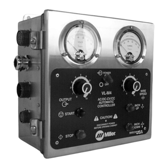
Miller VL-M4 Owner's Manual - Page 17
Browse online or download pdf Owner's Manual for Welding Accessories Miller VL-M4. Miller VL-M4 36 pages. Submerged arc controller for automatic welding

4-3. Connection Diagram
Customer must supply wire drive assembly and drive rolls, gun, welding wire, weld cables, and
Note
flux for the desired application.
17-Pin Shunt
Control Cord
14-Pin Welding
Power Source
Control Cord
Welding Cables
Flux Valve
5-Pin Motor
Control Cord
This unit is supplied with the 5-pin,
14-pin, and 17-pin cords. Select
the proper cord and make each of
the connections shown.
.
For non-Miller power sources
and wire drive motors, Term-
minal Strip TE2 can be used
for hookup (See Sections 3-9
and 3-10).
Route voltage sense lead through
strain relief on user access hole.
Connect one end to terminal 21 on
TE1 (see Section 4-6). Connect
other end of voltage sensing lead
to the workpiece.
Cord
Voltage
Sensing
Cord
OM-189 530 Page 13
