ABB Endura AZ40 Manual - Page 14
Browse online or download pdf Manual for Industrial Equipment ABB Endura AZ40. ABB Endura AZ40 16 pages. Oxygen and carbon monoxide equivalent (coe) analyzer
Also for ABB Endura AZ40: Operating Instruction (16 pages), Operating Instructions Manual (20 pages)

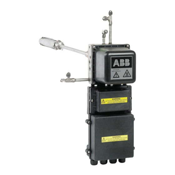
8.4 Flange block thermocouple – T/C 2
Referring to Fig. 8.5:
1. Use a small flat-bladed screwdriver to depress the spring
connectors at terminal numbers 16 and 18 and disconnect
flange block thermocouple T/C 2 wires from top terminal
block connectors A.
2. Pull thermocouple (T/C2) wires up through (right) opening
B in flange block C.
3. Use a small flat-headed screwdriver to unscrew cartridge
heater / thermocouple retainer screw D and remove
cartridge heater / thermocouple retainer E. Retain items
for re-use.
Do not disturb cartridge heater F.
4. Withdraw thermocouple G (T/C 2) from flange block C
and discard the thermocouple.
5. Slide the new thermocouple (T/C 2) into its chamber in
flange block C.
6. Carefully form the thermocouple through 90 ° so it fits into
the groove in retainer E.
IMPORTANT (NOTE)
The retainer (E) at this position has a notch used
to guide / restrain the thermocouple. Only use the
retainer
from this position when fitting / replacing
thermocouple T/C 2.
7. Apply a small amount of anti-seize compound (suitable for
temperatures up to 200 °C [392 °F]) to the thread of
cartridge heater / thermocouple retainer screw D and use
a small flat-headed screwdriver to secure cartridge heater
/ thermocouple retainer E to flange block C.
14
INS/ANAINST/008-EN Rev. B | Endura AZ40 | Sensor assembly | Heater and thermocouple kit
8. Feed both thermocouple (T/C2) wires down through right
opening B in flange block C and make terminal block
connections at the top connectors A as follows:
— connect one wire from thermocouple T/C2 to
terminal 16.
— connect one wire from thermocouple T/C2 to
terminal 18.
9. Refit sensor covers – refer to Section 7.2, page 8.
