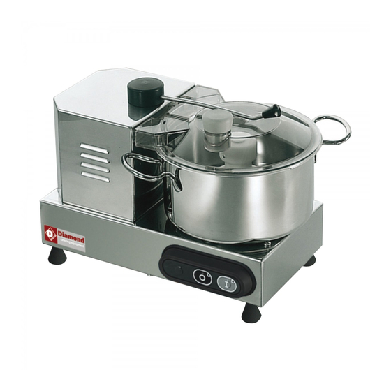
Diamond CSP/4 Manual - Page 6
Browse online or download pdf Manual for Commercial Food Equipment Diamond CSP/4. Diamond CSP/4 8 pages.

3.2 - PACKAGE CHECK UP ON RECEIPT
If no external damage is evident on the package upon its arrival, open it and check
that all the components are inside (see FIG. n°3). If the package has suffered
rough handling, bumps or crashes, the carrier must be informed about any
damage; moreover a detailed report on the extent of the damage caused to the
machine must be filled within three days from the delivery date shown in the
shipping documents. Do not overturn the package!! When the package is
transported, make sure the box is lifted by the 4 corners (parallel to the ground).
3.3 - PACKAGING DISPOSAL
The components of the packaging (cardboard, pallet, plastic straps and
polyurethane) are urban solid waste; therefore they can be easily disposed.
If the machine has to be installed in countries where specific regulations are in
force, packaging must be disposed in compliance with them.
CHAP. 4 - INSTALLATION
4.1 - SETTING UP OF THE MACHINE
The machine must be installed on a working table suitable for its overall
dimensions shown in Tab. 1 (in accordance with the model), therefore it must be
adequately large, well levelled, dry, smooth, resistant, stable.
Moreover the machine must be installed in a room with max. 75% not saline
humidity at a temperature between +5°C and +35°C; that is to say in a place that
does not provoke the machine failure.
4.2 - ELECTRICAL CONNECTIONS
Tha appliance is equipped with a power supply cord which section 3x1.5mm²,
length 1.5m with a "SUKO" plug.
Connect the appliance to 230 Volt 50 Hz, by interposing a differential-
magnetothermic switch of 10A, ∆ I = 0.03A. Check that the earthing is fully
operational. Moreover check that the features on the rating plate - serial number
(see FIG. n°4) correspond to the features shown in the consignment and delivery
note.
FIG. n°4 - Rating plate - serial number
8
4.3 - ELECTRIC DIAGRAMS
4.3.1 - Single-phase electric diagram
FIG. n°5 - Single-phase electric diagram.
4.3.2 - Single-phase electric diagram. CUTTER with speed dial knob.
FIG. n°6 - Single-phase electric diagram. CUTTER with speed dial knob.
4.4 - OPERATION CHECKS
Check the proper functioning of the machine according as follows:
1 press the start button "I" and the stop button "0";
2 check whether the machine stops after the lid has been removed;
3 in case of a CUTTER equipped with a speed dial knob, check whether the
number of rotations increases by adjusting the knob clockwise.
CHAP. 5 - USE OF THE MACHINE
5.1 - CONTROLS
Controls are placed on the CUTTER body as shown in the picture below.
NOTE: The speed dial knob (1) is installed only in the vv model.
9
