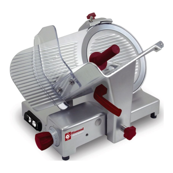
Diamond PL 300 Operating And Maintenance Manual - Page 6
Browse online or download pdf Operating And Maintenance Manual for Commercial Food Equipment Diamond PL 300. Diamond PL 300 16 pages. Professional slicer ce

2.2 -
POSITIONING
Position the pallet, with the slicer, on a
flat surface and take off (a) the sharpe-
ner from the slicer (Fig. n°12).
At this point turn the machine on its
side (Fig. n°13) and unscrew, with the
proper wrench provided, the 4 nuts
which fasten the slicer. Remove the 4
washers and unscrew the 4 fastening
tie rods on the wooden pallet. Take off
the pallet and fasten the 4 feet provi-
ded. Finally, put the sharpener in its
place.
Position the slicer in the predestined
place.
The dimensions indicated in Tab. 1
(according to the model) must be kept
in mind for the plane where the slicer
will be installed, therefore it must be
wide enough, well-levelled, dry, smo-
oth, robust, stable about 80 cm high off
the ground and at least 20 cm from
walls, objects, shelves, etc. (Fig. n°14)
in respect to the space necessary for
its use and safeguarding.
Furthermore the machine must be pla-
ced in an environment with a maximum
humidity of 75%, not salty and with a
temperature between +5°C and +35°C;
in any case in environments which do
not lead to deviations of the above.
Make sure the graduated handgrip is in
posiion "0".
Check the alignment of the blade-plane
thickness gauge by running a finger
(Fig. n°16) from the blade towards the
thickness gauge plane (never in the op-
posite direction). Unscrew and screw
the foot (1) until the correct alignment is
found (Fig. n°17), then screw the rub-
ber part (2) to fix everything (Fig. n°17).
Fig. n°12
Fig. n°13
20cm
20cm
20cm
20cm
~ 80cm
Fig. n°14
Fig. n°15
Fig. n°16
Fig. n°17
8
2.3 - ELECTRICAL CONNECTION
Check that the data reported on the
technical-part number plate (Fig. n°18),
the delivery documents and the order,
correspond; contact the supplier for cla-
rification if they do not.
At this point make sure that the system
is standard and that the cable and
grounding system perfectly operate.
2.3.1 - Slicer with single-phase motor
The slicer is equipped with a feeding cable with a cross section area of 3x1mm²;
length 1.5m and a "SHUKO" plug. Connect the 230 V. - 50 Hz slicer,
interposing a magnetothermic differential switch of 10A,= 0.03A.
2.3.2 - Slicer with 400 V. three-phase motor
The slicer is equipped with a feeding cable with a cross section area of 5x1mm²,
length 1.5m and a red 15A 3F + T CEI plug. Connect the slicer to the 400 V. -
50Hz three-phase supply mains, interposing a magnetothermic differential switch
of 10 A, =0.03A.
2.3.3 - Slicer with 230 V. three-phase motor
The slicer is equipped with a feeding cable with a section area of 5x1mm²; length
1.5m and a blue 15A 3F + T CEI plug.
Connect the slicer 230 V. - 50 Hz three-phase supply mains, interposing a
magnetothermic differential switch of 10A,= 0.03A.
Check that the direction of the blade rotation is counter-clockwise looking at the
slicer from the side of the bladeguard. If not proceed as in par. 2.3.4.
2.3.4 - Blade rotation direction
Check the direction of the blade
rotation with a pulse of the "I" push-
button (ON), immediately followed by
the "0" push-button OFF.
The direction of the blade rotation must
1
be counter-clockwise when looking at
2
the slicer from the bladeguard side (Fig.
n°19). In the case that the rotation
direction is not exact, invert (Fig. n°20)
Fig. n°18
Fig. n°19
9
