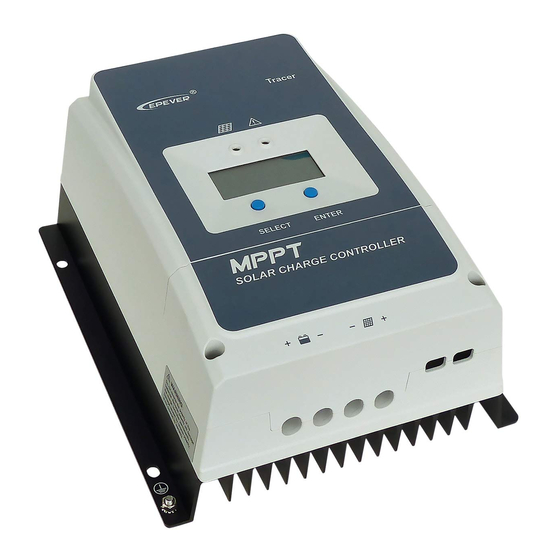
Epever TRACER 6420 Quick Start Manual
Browse online or download pdf Quick Start Manual for Controller Epever TRACER 6420. Epever TRACER 6420 8 pages.

Converting the Frequency Plan of a TRACER 6420 System
Introduction
TRACER 6420 systems are shipped from the factory with the frequency plan programmed as Plan A or Plan B.
Each wireless link must contain a Plan A radio on one end and a Plan B on the other. A frequency plan
conversion may be performed in the field, but should only be attempted if absolutely necessary and must
always be performed by qualified personnel. This document outlines the procedure for changing the frequency
plan of a TRACER 6420 system.
This document contains digital images showing connectors, cable routings, etc. Connector
placement and cable routings in the images will not be identical to your TRACER 6420
system. Follow the written procedure provided in this guide and refer to the images only
when instructed.
Prerequisite Procedures
Disconnect all cables attached to the TRACER 6420 system (including power, data,
terminal RS-232, etc.) before performing this procedure.
The current frequency plan configuration is listed on a label located on the rear panel of the unit (near the
Antenna connector). Record the current configuration before beginning this procedure.
Tools and Materials Required
Do not attempt to perform the conversion without the proper tools (see list below). Using
improper tools will damage the unit.
•
5/16" Torque wrench (8 in-lbs)
•
3/16" nut driver
•
Phillips-head screw driver
Electronic equipment can be damaged by static electrical discharge. Before handling
equipment, put on an antistatic discharge wrist strap to prevent damage to components.
Place equipment in antistatic packing material when transporting or storing. When
working on equipment, always place it on an approved antistatic mat that is electrically
grounded.
612806420L1-18A
August 2005
1
