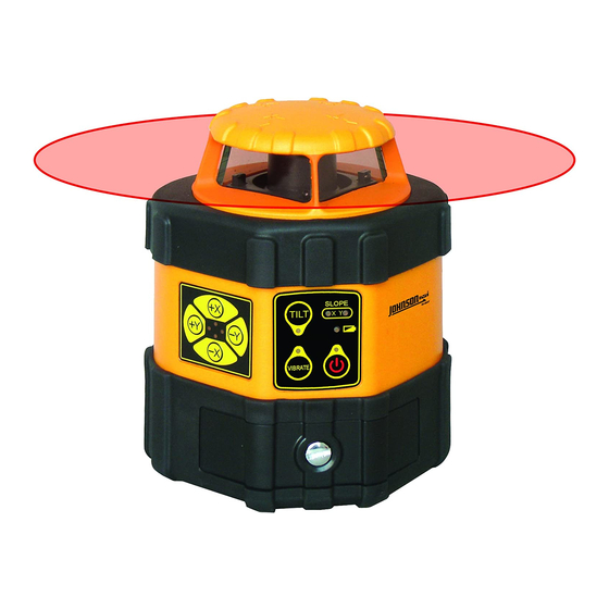
AccuLine 40-6537 Service Manual - Page 4
Browse online or download pdf Service Manual for Measuring Instruments AccuLine 40-6537. AccuLine 40-6537 15 pages. Auto-leveling rotating laser
Also for AccuLine 40-6537: Instruction Manual (18 pages)

2.3 Main Body Assembly (AP1941)
Item JLT Part #
6.1
AP1513
M3 x 8 Cross Plate Screw
6.2
AP1955
Top Plate Assembly
6.3
AP1883
3MM Elastic Gasket
6.4
AP1956
Core Assembly
6.5
AP1957
Tension Spring
6.6
AP1958
#1 Main PCB
6.7
AP1616
M2.5 x 5 Cross Plate Screw
6.8
AP1959
Frame Part 1
6.9
AP1960
Bottom Plate
6.10
AP1961
#8 Alarm PCB
6.11
AP1962
Spacer
6.12
AP1493
M2.5 x 8 Cross Plate Screw
6.13
AP1963
#4 PCB
6.14
AP1964
Connecting Staff Part
6.15
AP1965
#5 PCB
6.16
AP1915
2.5MM Elastic Gasket
6.17
AP1966
Frame Part 2
6.18
AP1967
4MM Elastic Gasket
6.19
AP1968
M4 x 14 Cross Plate Screw
1.
Remove #4 PCB (6-13) and #5 PCB (6-15) by loosening/removing retaining 6 screws (6-7) and 2 elastic gaskets (6-16)
respectively.
2.
Remove #1 PCB (6-6) by loosening/removing 4 retaining screws (6-7).
3.
Disassemble top plate assembly (6-2) by removing retaining screw (6-19) and respective elastic gasket (6-18) as well as 6
retaining screws (6-1) and respective elastic gaskets (6-3).
4.
Remove Core Assembly (6-4) from Frame Parts 1 and 2 (6-8 and 6-17, respectively) by removing 2 tension springs (6-5).
5.
Disassemble Frame Parts 1 and 2 (6-8 and 6-17, respectively) by removing 6 retaining screws (6-12) and they're respective
elastic gaskets (6-3).
6.
Disassemble #8 Alarm PCB (6-10) by removing 2 retaining screws (6-12) and they're respective spacers (6-11)
Prepared By: Tim Wojo
Description
Qty
12
1
12
1
2
1
10
1
1
1
2
2
1
1
1
2
1
1
1
Revision - Date: 0 – 03232009
40-6537 Service Manual
Page 4 of 15
