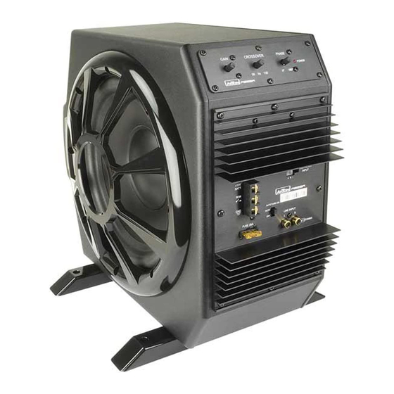
AXTON AB25A Installation Manual - Page 14
Browse online or download pdf Installation Manual for Subwoofer AXTON AB25A. AXTON AB25A 20 pages. 10" active subwoofer

3. MOUNTING OF THE ACTIVE SUB
Attention! For your own safety, disconnect the negative battery terminal (-12V), before you
start any wiring work!
The mounting location should be carefully selected, and in the interest of passive driver and
passenger safety, this active subwoofer must be securely mounted.
Once the location where the active subwoofer will be mounted is clear, use the unit as a
template for the marking of the mounting holes with pencil or felt-tip marker. The mounting
holes should be pilot-drilled, using a 2,5 mm or 3mm drill bit.
4. CABLE ROUTING AND WIRING
4.1 POWER WIRES
Use power cables with at least 10 mm² cross section. Run the positive main power cable
(„+12 V") directly from the positive terminal of the car battery to the AB25A. For protection
of your car audio system against electrical fire hazards, resulting from a short-circuit of the
main power cable to chassis ground, a main fuse holder must be inserted within the first
30 cm of the positive main power cable. The applicable fuse value must be matched to the
limitations of your main power cable and the current draw of the amp-module – therefore
choose an appropriate fuse value, but no less than 30 A.
– 14 –
