Digilent PLTW S7 Reference Manual - Page 8
Browse online or download pdf Reference Manual for Motherboard Digilent PLTW S7. Digilent PLTW S7 11 pages.

PLTW S7 Reference Manual
7
DIP Header
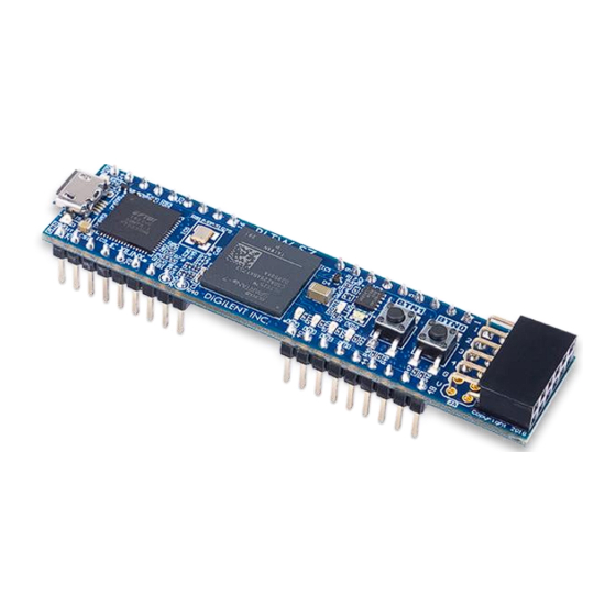
The PLTW S7 has a 48-pin DIP form factor connector, implemented as four 9-pin headers for connecting to
breadboards and custom fixtures. The pins have 100 mil spacing, and the entire module is 0.7 inches by 3.05
inches. Headers J1 and J3 are separated by 700 mil lengthwise along the board, measured from the center of the
innermost pins, as are headers J2 and J4. Headers J1 and J2 are separated by 600 mil across the board, as are
headers J3 and J4. Of the 48 possible pin locations, 36 are populated on the four headers. Of these, 32 are directly
connected to FPGA Digital I/Os, 2 are voltage-divided and connected to FPGA analog inputs, and two are
connected to power pins. The pin and header numbers are shown in Figure 7.1.
Copyright Digilent, Inc. All rights reserved.
Other product and company names mentioned may be trademarks of their respective owners.
Figure 6.1. PLTW S7 Basic I/O.
Page 8 of 11
