Siemens SINAMICS G130 Operating Instructions Manual - Page 32

Browse online or download pdf Operating Instructions Manual for Industrial Equipment Siemens SINAMICS G130. Siemens SINAMICS G130 46 pages. Line filter
Also for Siemens SINAMICS G130: Operating Instructions Manual (24 pages), Operating Instructions Manual (26 pages), Operating Instructions Manual (24 pages), Operating Instructions Manual (31 pages), Operating Instructions Manual (30 pages), Operating Instructions Manual (28 pages), Operating Instructions Manual (30 pages), Operating Instructions Manual (22 pages), Operating Instructions Manual (28 pages), Operating Instructions Manual (30 pages), Operating Instructions Manual (34 pages), Operating Instructions Manual (46 pages), Operating Instructions Manual (26 pages), Operating Instructions Manual (26 pages), Operating Instructions Manual (28 pages), Operating Instructions Manual (42 pages), Operating Instructions Manual (46 pages), Operating Instructions Manual (24 pages), Operating Instructions Manual (24 pages), Operating Instructions Manual (30 pages), Operating Instructions Manual (42 pages), Operating Instructions Manual (38 pages), Operating Instructions Manual (46 pages), Operating Instructions Manual (28 pages), Operating Instructions Manual (22 pages), Operating Instructions Manual (24 pages)
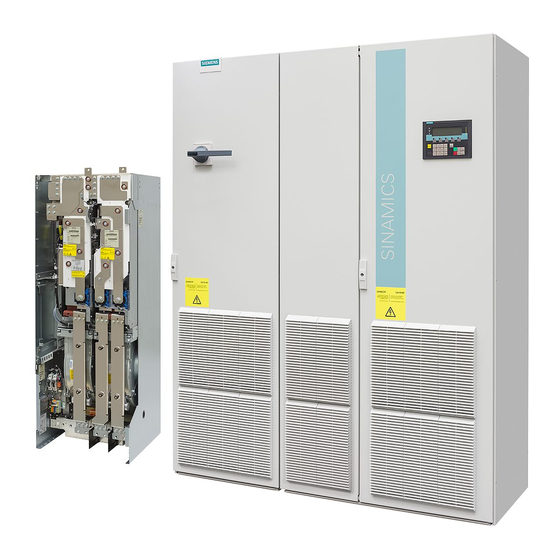
Siemens SINAMICS G130 Operating Instructions Manual
Connection
4.2 Connecting the Braking Module
Digital inputs/outputs X21
Table 4- 3
Terminal block X21
Terminal
1
2
3
4
5
6
Max. connectable cross-section 1.5 mm
DI: digital input; DO: Digital output
1)
Note
When the Braking Module is installed, the individual terminals on its X21 terminal block are
positioned as follows: terminal "1" is at the rear, terminal "6" at the front.
Note
Applying a high signal to terminal X21.3 inhibits the Braking Module. With a falling edge,
pending fault codes are acknowledged.
Threshold switch
The response threshold at which the Braking Module is activated and the DC link voltage
generated during braking are specified in the following table.
The threshold switch must only be used when the Power Module is switched off and the DC
link capacitors are discharged.
30
Designation
1)
Shield
0 V
DI inhibit input
0 V
DO fault output
+24 V
2
WARNING
Technical data
Shield connection for terminals 2 ... 6
High signal level: +15 V to 30 V
Current consumption: 2 mA to 15 mA
Low signal level: -3 V to 5 V
High signal: No fault
Low signal: Fault present
Voltage: 24 V DC
Load current: 0.5 A to 0.6 A
Voltage: +18 V to +30 V
Typical current consumption (induced current consumption):
10 mA at 24 V DC
Operating Instructions, 03/2012, A5E00331454A
Braking Module / braking resistor