Siemens SINAMICS G130 Operating Instructions Manual - Page 33

Browse online or download pdf Operating Instructions Manual for Industrial Equipment Siemens SINAMICS G130. Siemens SINAMICS G130 46 pages. Line filter
Also for Siemens SINAMICS G130: Operating Instructions Manual (24 pages), Operating Instructions Manual (26 pages), Operating Instructions Manual (24 pages), Operating Instructions Manual (31 pages), Operating Instructions Manual (30 pages), Operating Instructions Manual (28 pages), Operating Instructions Manual (30 pages), Operating Instructions Manual (22 pages), Operating Instructions Manual (28 pages), Operating Instructions Manual (30 pages), Operating Instructions Manual (34 pages), Operating Instructions Manual (46 pages), Operating Instructions Manual (26 pages), Operating Instructions Manual (26 pages), Operating Instructions Manual (28 pages), Operating Instructions Manual (42 pages), Operating Instructions Manual (46 pages), Operating Instructions Manual (24 pages), Operating Instructions Manual (24 pages), Operating Instructions Manual (30 pages), Operating Instructions Manual (42 pages), Operating Instructions Manual (38 pages), Operating Instructions Manual (46 pages), Operating Instructions Manual (28 pages), Operating Instructions Manual (22 pages), Operating Instructions Manual (24 pages)
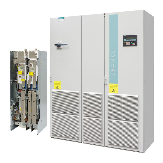
Siemens SINAMICS G130 Operating Instructions Manual
Table 4- 4
Response thresholds of the Braking Modules
Rated voltage
Response
threshold
380 V – 480 V 3 AC
673 V
774 V
500 V – 600 V 3 AC
841 V
967 V
660 V – 690 V 3 AC
1070 V
1158 V
Note
The threshold switches of the Braking Modules are positioned on the panel as follows:
• Braking Modules for frame sizes FX and GX: position "1" is up; position "2" is down
• Braking Modules for frame sizes HX and JX: position "1" is back; position "2" is front
CAUTION
Even when the response threshold is set to a low value, the DC link voltage can still reach
the maximum voltage value (hardware shutdown threshold), thus triggering the
"Overvoltage" fault. This can occur, for example, in cases where there is too much
regenerative energy for the available braking power.
To prevent the DC link voltage from exceeding the threshold, the Vdc-max controller must
be enabled (p1240) and the device supply voltage set accordingly (p0210).
Braking Module / braking resistor
Operating Instructions, 03/2012, A5E00331454A
Switch
position
1
774 V is the delivery condition setting. With line voltages of between 380 V
and 400 V, the response threshold can be set to 673 V to reduce the
2
voltage stress on the motor and converter. This does, however, reduce the
possible braking power with the square of the voltage (673/774)² = 0.75.
The maximum possible braking power is, therefore, 75%.
1
967 V is the delivery condition setting. With a line voltage of 500 V, the
response threshold can be set to 841 V to reduce the voltage stress on the
2
motor and converter. This does, however, reduce the possible braking
power with the square of the voltage (841/967)² = 0.75.
The maximum possible braking power is, therefore, 75%.
1
1158 V is the delivery condition setting. With a line voltage of 660 V, the
response threshold can be set to 1070 V to reduce the voltage stress on
2
the motor and converter. This does, however, reduce the possible braking
power with the square of the voltage (1070/1158)² = 0.85.
The maximum possible braking power is, therefore, 85%.
4.2 Connecting the Braking Module
Comment
Connection
31