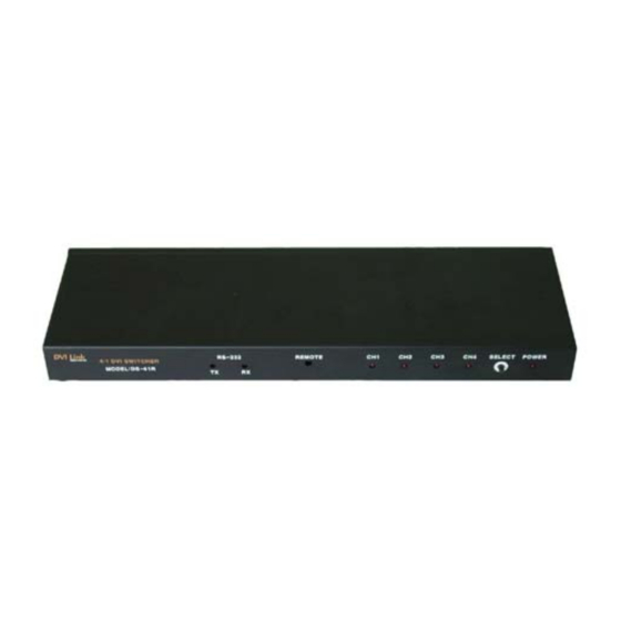
Digital Extender DS-41R User Manual - Page 6
Browse online or download pdf User Manual for Switch Digital Extender DS-41R. Digital Extender DS-41R 12 pages. Dvi switcher

3 Video Connection
VIDEO CONNECTION
1. Connect your video source's DVI output port to the DVI switch's DVI input port using standard
DVI cables(not included). Make sure all your DVI sources and the display is turned off before
connecting the cables)
2. Connect your DVI display's DVI input port to DVI switch's DVI output port. Make sure your DVI
display is turned off before connecting the cables)
3. Plug the 5V power supply into the switch's power input port.
4. Plug the 5V wall mount power supply into the wall outlet.
5. Turn on your display.
6. Turn on your video sources.
7. Use your remote control unit to switch channels. Or use the select button on the front panel of
the switch to change channels.
RS232 CONTROL CONNECTION
RS232 connection allows the user to interface the DVI LINK switch with a serial port on a computer
or other control device. The computer or other control device may require additional software for
various control functions.
RS232 Control Information
Our DS-21R and DS-41R use pin#2 and #3 and the assignments are as follows;
Control computer's RS232 pin# 2 is connected to our DVI switch's pin#3
Control computer's RS232 pin# 3 is connected to our DVI switch's pin#2
Baud rate: 9600, Data bits: 8, Stop Bits: 1, Parity: None, Flow control: None
The control protocols are as follows;
Channel 1 request is ascii code "@001*" and the response back to the computer is "!"
Channel 2 request is ascii code "@002*" and the response back to the computer is "!"
Channel 3 request is ascii code "@003*" and the response back to the computer is "!"
Channel 4 request is ascii code "@004*" and the response back to the computer is "!"
Copyright 2006 RTcomUSA., Inc.
6
