Cisco ASA 5508-X Manual - Page 3
Browse online or download pdf Manual for Network Hardware Cisco ASA 5508-X. Cisco ASA 5508-X 14 pages. Threat defense reimage guide
Also for Cisco ASA 5508-X: Hardware Installation Manual (32 pages), Quick Start Manual (8 pages), Easy Setup Manual (11 pages), Quick Start Manual (9 pages), Software Manual (37 pages), Mount And Connect (6 pages)
Overview
Front Panel
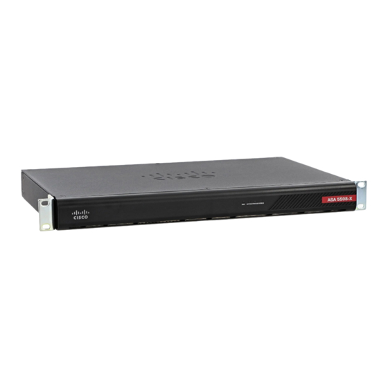
The following figure shows the front panel of the ASA 5508-X. The ASA 5516 has an identical front panel.
There are four LEDS on the front panel. See
Figure 2: ASA 5508-X and ASA 5516-X Front Panel
Rear Panel
The following figure shows the rear panel of the Cisco ASA 5508-X and ASA 5516-X.
Figure 3: ASA 5508-X and ASA 5516-X Rear Panel
1
3
5
Power switch
Standard rocker-type power on/off switch
Status LEDs
The locations and meanings of the status LEDs
are described in
LEDs, on page
Management port
A Gigabit Ethernet interface restricted to network
management access only. Connect with an RJ-45
cable.
LEDs, on page 4
for the descriptions.
2
Power cord socket
The chassis power-supply socket. See
Supply Modules, on page 7
information about the ASA power supply.
4
Network data ports
Eight Gigabit Ethernet RJ-45 (8P8C) network I/O
4.
interfaces. The ports are numbered (from left to
right) 1, 2, 3, 4, 5, 6, 7, 8. Each port includes a
pair of LEDs, one each for connection status and
link status. The ports are named and numbered
Gigabit Ethernet 1/1 through Gigabit Ethernet
1/8. See
information.
6
Console ports
Two serial ports, a mini USB Type B, and a
standard RJ-45 (8P8C), are provided for
management access via an external system. See
Console Ports, on page 6
information.
Front Panel
for more
Network Ports, on page 6
for additional
for additional
Overview
Power
3