ECKELMANN LICANYKAB Operating Instructions Manual - Page 7
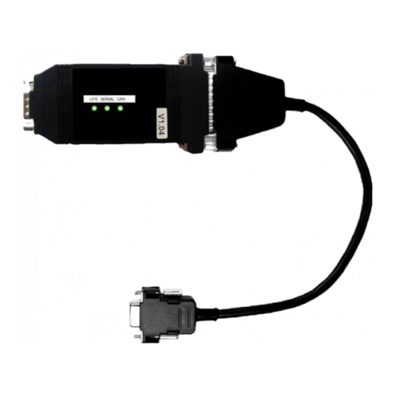
Browse online or download pdf Operating Instructions Manual for Adapter ECKELMANN LICANYKAB. ECKELMANN LICANYKAB 12 pages. Can bus-pc adapter

LAN Gateway Firmware V1.1c
3. Connect the CAN bus cable to the COMBICON plug (see table 3.1-1 / picture 3.1-2).
Picture 3.1-2: Wire assignment for the connection of the COMBICON plug to the CAN bus (pictured without
through looping)
For safe operation it is sufficient to connect the signals CAN-low, CAN-high and
CAN-GND to the Sub-Min-D plug.
The additional use of the CAN-SHLD in the Sub-Min-D plug can cause problems as
the E•LDS system's CAN bus uses CAN-SHLD and CAN-GND differently, although
these signals are connected internally within the adapter!
Incorrect shielding can lead to electromagnetic noise fields. During wiring work, it is
essential that the conductors be connected by a professional and correctly shielded.
If the CAN bus to PC adapter is not positioned at the end of the CAN bus, then the
cable must be looped through from the Sub-Min-D plug.
The terminating resistor in picture 3.1-1 is obsolete and is to be attached to the end
of the CAN bus (on the last node).
© 2010 – ECKELMANN AG | BERLINER STRASSE 161 | 65205 WIESBADEN | FON +49(0)611 7103-0 | FAX +49(0)611 7103-133 | eckelmann.de
V1.2
03. May 2010
7/12
