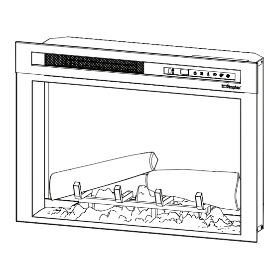
Dimplex XHD28G Service Manual - Page 11
Browse online or download pdf Service Manual for Indoor Fireplace Dimplex XHD28G. Dimplex XHD28G 14 pages.
Also for Dimplex XHD28G: Owner's Manual (18 pages), Service Manual (14 pages), Service Manual (16 pages)

8. Secure the wire connector by crimping the 3M symbol
with pliers. Pull on both wires to ensure a strong
connection.
9. Repeat the process for the 4 remaining wires, ensuring
that all wires are paired by colour in each connector.
10. Attach new flicker motor to the retaining bracket.
11. Insert stem from flicker rod into the rubber grommet.
12. Reattach the flicker rod retaining bracket.
13. Reassemble the firebox.
Figure 4
Heater assembly screws
Media bed/Log
Flame screen retaining
set screws
bracket screws
Flicker Rod Replacement
Tools Required: Phillips head screwdriver
WARNING: If the firebox was operating prior to
servicing, allow at least 10 minutes for the heating
elements to cool off to avoid accidental burning of skin.
WARNING: Disconnect power before attempting any
maintenance to reduce the risk of electric shock or injury to
persons.
1. Follow the instructions for accessing the bottom
components on pages 8-9.
2. Remove the left side flicker rod retaining bracket by
unscrewing the two screws from the back of the firebox.
(Figure 4)
3. Pull the old flicker rod out from the rubber grommet.
4. Insert new flicker rod.
5. Place bracket over the end of the new flicker rod and
reaffix the bracket to the firebox.
6. Reassemble the firebox.
Remove this bracket when
changing icker rod
Remove this bracket when
changing icker motor
Flame LED Strip Replacement
Tools Required: Phillips head screwdriver
WARNING: If the firebox was operating prior to
servicing, allow at least 10 minutes for the heating
elements to cool off to avoid accidental burning of skin.
WARNING: Disconnect power before attempting any
maintenance to reduce the risk of electric shock or injury to
persons.
1. Follow the instructions for accessing the bottom
components on pages 8-9.
2. Locate the plastic LED holder bar and remove the
screw on either side (2 total).
3. Disconnect the wire(s) that are connected to the LED
strip(s) on the LED holder. The LED holder can now be
removed.
4. Remove the 4 screws that secure the LED strip to the
LED holder.
5. Install new board by reinserting the screws and
connecting the cable(s).
6. Properly orient and install the LED holder, ensuring that
the flame LEDs are facing the flicker rod.
7. Reassemble the firebox.
Flame Base LED Strip Replacement
Tools Required: Phillips head screwdriver
Flathead Screwdriver
WARNING: If the firebox was operating prior to
servicing, allow at least 10 minutes for the heating
elements to cool off to avoid accidental burning of skin.
WARNING: Disconnect power before attempting any
maintenance to reduce the risk of electric shock or injury to
persons.
1. Follow the instructions for accessing the bottom com-
ponents on pages 8-9.
2. Locate the plastic LED holder bar and remove the
screw on either side (2 total)
3. Disconnect the two cables that lead to the LED strips.
4. The LED holder can now be removed
5. Release the LED strip from the clips: starting at one
end of the LED strip, carefully place the head of the
flathead screwdriver under the LED strip while gently
pulling it up and out to release it from the clips on the
LED holder.
6. Snap the new LED strip into place and reconnect the
cable.
7. Connect both cables. Properly orient and install the
LED holder, ensuring that the flame base LEDs are
toward the base of the firebox and the flame LEDs are
facing the flicker rod.
8. Reassemble the firebox.
11
