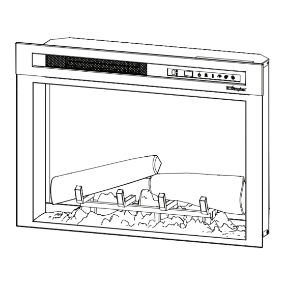
Dimplex XHD28G Service Manual - Page 9
Browse online or download pdf Service Manual for Indoor Fireplace Dimplex XHD28G. Dimplex XHD28G 14 pages.
Also for Dimplex XHD28G: Owner's Manual (18 pages), Service Manual (14 pages), Service Manual (16 pages)

4. Carefully lay the fireplace on its back.
5. Remove the bottom panel and set it aside.
!
NOTE: On the XHD28G, the media bed lights
are attached to this bottom panel. You can disconnect
these lights to have better access to the components in
the firebox.
!
NOTE: The log set/media tray has a wire attached
to the unit which can be temporarily disconnected for
easier access.
Most components can now be accessed for service.
However, if you wish to have further access to the
components, complete the following steps.
6. Remove the flame screen retaining brackets by
removing the 2 screws on each side of the firebox that
hold each bracket (4 screws total). (Figure 4)
7. Carefully slide the flame screen down toward the base
of the firebox and set it aside during service.
!
NOTE: When reinserting the flame screen, ensure
that the upper portion is inserted all the way to the top.
Power Cord Replacement
Tools Required: Phillips head screwdriver
Pliers
7mm Wrench
WARNING: If the firebox was operating prior to
servicing, allow at least 10 minutes for the heating
elements to cool off to avoid accidental burning of skin.
WARNING: Disconnect power before attempting any
maintenance to reduce the risk of electric shock or injury
to persons.
1. Follow the instructions for accessing the top
components on page 8.
2. Disconnect the wires from the powercord, noting their
original locations. Use wrench to remove gold nut that
secures the green grounding wire to the body of the
firebox, along with the silver ring. Cut the cable ties as
needed to remove the wires.
3. With pliers, grasp the power cord strain relief grommet
from inside the back of the bottom panel and push
while twisting to remove.
4. Install the new power cord and reconnect wires as
before. Refer to the wiring diagram if needed. Ensure
that they are secure and the wires cannot be pulled out
of the wire connector.
WARNING: Ensure wires do not come in contact
with moving parts by securing wires in cable ties or
electrical tape.
5. Reassemble the firebox.
Main Control Board Replacement
Tools Required: Phillips head screwdriver
Pliers
WARNING: If the firebox was operating prior to
servicing, allow at least 10 minutes for the heating
elements to cool off to avoid accidental burning of skin.
WARNING: Disconnect power before attempting any
maintenance to reduce the risk of electric shock or injury
to persons.
1. Follow the instructions for accessing the top
components on page 8.
!
NOTE: It is recommended to take a picture of the
wiring connections on the main control board prior to
starting to ensure that all wires are reconnected to the
correct place on the board.
2. Disconnect all wire leading into the main control board.
It may be helpful to use pliers to disconnect the flag
connectors. Cut the cable ties as needed to remove the
wires.
3. Using pliers, pinch each of the four plastic standoffs to
depress the tabs while gently lifting the main control
board to release it.
4. Properly orient and install the new main control board.
5. Reconnect the wiring. Refer to the wiring diagram if
needed.
WARNING: Ensure wires do not come in contact
with moving parts by securing wires in cable ties or
electrical tape.
6. Reassemble the firebox.
Power Supply Replacement
Tools Required: Phillips head screwdriver
Pliers
WARNING: If the firebox was operating prior to
servicing, allow at least 10 minutes for the heating
elements to cool off to avoid accidental burning of skin.
WARNING: Disconnect power before attempting any
maintenance to reduce the risk of electric shock or injury to
persons.
1. Follow the instructions for accessing the top
components on page 8.
2. Locate the power supply and disconnect the wiring
connections, noting their original locations. Cut the
cable ties as needed to remove the wires.
3. Remove the 4 screws that secure the power supply
holder.
4. Properly orient and position the new power supply and
secure it by screwing the power supply holder into its
place.
5. Reconnect the wiring. Refer to the diagram if needed.
WARNING: Ensure wires do not come in contact
9
