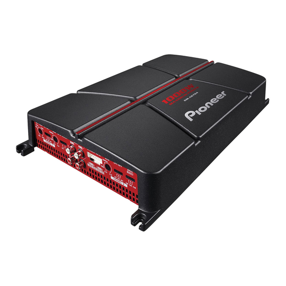
Pioneer GM-A6704 Owner's Manual - Page 8
Browse online or download pdf Owner's Manual for Amplifier Pioneer GM-A6704. Pioneer GM-A6704 19 pages. Bridgeable four-channel power amplifier
Also for Pioneer GM-A6704: Owner's Manual (33 pages)

- 1. Information to User
- 2. After-Sales Service for Pioneer Products
- 3. If You Experience Problems
- 4. Visit Our Website
- 5. The Safety of Your Ears Is in Your Hands
- 6. About Bridged Mode
- 7. Before Connecting the Amplifier
- 8. About Suitable Specification of Speaker
- 9. Connecting the Speakers
- 10. Connections When Using the RCA Input Jack
- 11. Connections When Using the Speaker Input Wire
- 12. Connecting the Power Terminal
- 13. Connecting the Speaker Output Terminals
- 14. Before Installing the Amplifier
- 15. Example of Installation on the Floor Mat or Chassis
- 16. Specifications
(Connecting the units
)
Please see the following sect1on for speaker
connection
inst~-uct1ons.
Refer to Connections
when using the speaker input wire.
9 Speake~-
output terminals
Please see the following section for speaker
connection instructions. Refer to Connecting
the speakers.
10
System remote control wire (sold separately)
Connect male terminal of this wire to the sys-
tem
~-emote
control terminal of the car
ste~-eo.
The female term 1 nal can be connected to the
auto-antenna relay control terminal. If the car
stereo lacks a system remote control terminal,
connect the male terminal to the power term-
inal v1a the 1gnition switch.
Fuse 25 Ax 2 (GM-A6704)
I
30 Ax 1 (GM-
A4704)
Fuse (30 A) x 2
Grommet
Rear side
J~
Front side
Note
INPUT SELECT (input select) switch must be set.
Fot- detai Is. see Setting the un/t. ~
Before connecting the
amplifier
A
wARNING
• Secure the wiring with cable clamps or adhe-
sive tape. To protect the wiring, wrap sections
in contact with metal parts in adhesive tape.
•
Never cut the insulation of the power supply
to feed power to other equipment. Current ca-
pacity of the wire is limited.
A
cAUTION
•
Never shorten any wires, the protection circuit
may malfunction.
•
Never wire the speaker negative cable directly
to ground.
•
Never band together multiple speaker's nega-
tive cables.
En
•
If the system remote control wire of the arrlpli-
fier is connected to the power term mal via the
1gnition sw1tch (12 V DC). the amplif1er w1ll re-
main on w1th the ignition
whethe~-
the car
stereo is on or off. which may exhaust battery
if the eng me is at rest or 1dling.
•
Install and route the separately sold battery
wire as far as possible hom the speaket- wit-es.
Install and
~-oute
the separately sold battery
wire. ground wire, speaker wires and the am-
plifiet- as far away as possible from the anten-
na, antenna cable and tuner.~
About bridged mode
Diagram A - Proper
LEE)
RO
Pioneer
Amplifier
4
Q
Bndged Mode
Diagram B- Improper
L<±>
R0
Pioneer
Amp!lfier
2 Q Bndged Mode
•
Do not install or use this amplifier by wiring
speakers rated at 4
n
(or lower) in parallel to
achieve a 2
n
(or lower) bridged mode (Dia-
gram B).
Am pi ifier damage, smoke, and overheating
could result from improper bridging. The am-
plifier surface could also become hot to the
touch and minor burns could result.
To properly install or use a bridged mode and
achieve a 4[2 load, wire two
sn
speakers in
parallel with Left® and Right
8
(Diagram A)
or use a single 4D speaker.
In addition, refer to the speaker i nstruct1on
manual for information on the correct con nec-
tion procedure.
•
For any further enquiries, contact your local
authorized Pioneer dealer or customer
service.~
