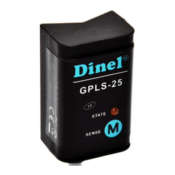
Dinel GPLS-25 Series Instruction Manual - Page 6
Browse online or download pdf Instruction Manual for Switch Dinel GPLS-25 Series. Dinel GPLS-25 Series 14 pages. Thru-wall level switches
Also for Dinel GPLS-25 Series: Instruction Manual (12 pages)

7 . Electrical connection
THE TYPE OF SENSOR GPLS – 25N – _ - S
Positive pole (+U) of power supply is connected through a load (relay) to brown wire or pin
connector No. 1, negative pole is connected to while wire or pin connector No.3.
THE TYPE OF SENSOR GPLS – 25N – _ - P
Positive pole (+U) of power supply is connected to brown wire or pin connector No.1, negative
pole is connected to blue wire or pin connector No.3. Load (relay) is connected to black wire or
pin connector No.2.
The sensor GPLS-28 output is protected againts short circuits. Capacity loads and loads with
low sleep resistance (bulb) the sensor evaluation as a short circuit. In case of high ambient
electromagnetic interference, parallel conductors with power lines, or lines at distances greater than
30 m, we recommend to use shielded cable.
Electrical connection must be done in de-energized state!
For switching supply sources, it is necessary to check that the input is galvanically separated
from the network side and that they are fitted with a filter suppressing the conforming
interference (terminals + and – oscillate together towards the ground potential), or the
interference is removed in another manner.
6
Connection scheme of sensor
with "S" type output
Connection scheme of sensor
with "PNP" type output
Legend:
(1) – Terminals number for variants with connector
BN – Brown
WH – White
BU – Blue
GPLS-25
© Dinel, s.r.o.
