Alderon Industries VersAlarm 4X Operation, Maintenance And Installation Manual - Page 5
Browse online or download pdf Operation, Maintenance And Installation Manual for Security System Alderon Industries VersAlarm 4X. Alderon Industries VersAlarm 4X 6 pages. 2-zone outdoor
Also for Alderon Industries VersAlarm 4X: Operation, Maintenance And Installation Manual (3 pages)

VersAlarm
2-Zone | Outdoor Alarm System, Type 4X
Operation, Maintenance and Installation Manual
Testing
Make sure all steps of the installation process are completed and there is
power to the product. When powered, the green LEDs should illuminate.
Test monthly to ensure system integrity.
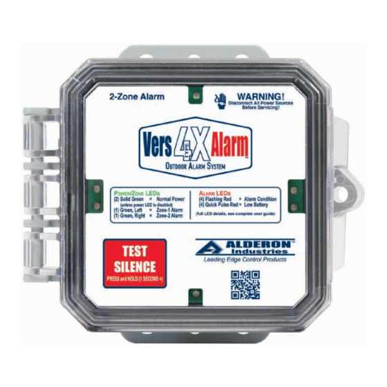
1. To test alarm function, press and hold (1-second +) the test/silence
button (Fig. 7), the red alarm LEDs should illuminate (flashing) with the
green power/zone indicator LEDs illuminated (solid), buzzer should
annunciate in a pulse tone, and auxiliary contacts should activate.
2. The sensors (signaling device) should be connected to the alarm
terminals labeled ALM1 and ALM2 on the alarm circuit board. Activate
each sensor separately, the red alarm LEDs should illuminate (flashing)
and the green zone indicator LED should illuminate (solid) for zone-1
(left) and zone-2 (right), buzzer should annunciate in a pulse tone, and
the auxiliary contacts should activate.
3. To test alarm silence function, activate the sensor for zone-1 to simulate
an alarm condition, then press/hold (1-second +) the test/silence button
and the buzzer should silence while the alarm LEDs remain illuminated,
flashing and the left green zone indicator LED should remain
illuminated (solid). Then, deactivate the sensor, the alarm condition
should clear and the alarm should auto reset for the next alarm cycle.
Repeat this process for the zone-2 sensor.
4. Models with a pump terminal block, the pump should be off once power
is applied and the pump switch is deactivated. Activate the pump switch
and the pump should turn on. Repeat to ensure switch works properly.
Alarm Systems
Control Panels
Alderon Industries - Hawley, MN | 218.483.3034 | [email protected] | alderonind.com
4X
™
Float Switches
Leak Detection Systems
(Fig. 7)
Notes: Place finger in the center of the test/silence capacitive
touch button to activate, button sensor will ignore edge touches.
To disable the green power LEDs, press and hold the test/silence
button for approximately 8-seconds. The green LEDs will pulse
three times and the green power LED indicators will turn off.
Repeat this process to turn them back on.
P/N: QSG00307_Rev01
Page 5 of 6
