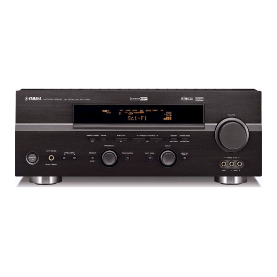
Yamaha HTR-5740 Service Manual - Page 11
Browse online or download pdf Service Manual for Receiver Yamaha HTR-5740. Yamaha HTR-5740 39 pages. Av receiver/av amplifier

- 1. Contents
- 2. Service Manual
- 3. Set Menu Table
- 4. Internal View
- 5. Block Diagram
- 6. Printed Circuit Board (Foil Side)
- 7. Schematic Diagram
- 8. Schematic Diagram (Operation)
- 9. Schematic Diagram (Main)
- 10. Schematic Diagram (Power)
- 11. Schematic Diagram (Subtrans)
- 12. Schematic Diagram (Video)
- 13. Exploded View
A
B
I
1
FUNCTION (3) P. C. B. (Surface Mount Device)
2
9
8
16
1
3
1
8
4
5
4
5
4
8
1
9
8
8
7
14
1
16
1
5
6
• Semiconductor Location
Ref. no. Location
Ref. no. Location
D601
B4
IC606
A5
D602
B5
IC607
B4
D603
B5
IC608
A3
D604
B5
IC609
B5
Circuit No.
D606
A5
Q751
I6
C772
D607
C4
Q752
I6
Q751, 752, 754, 755
D608
C4
Q753
I6
R760, 761, 771-774, 779, 780, 782, 783
D609
C4
Q754
I6
R785, 786, 788, 789, 791
D610
C5
Q755
I6
X: NOT USED
IC603
A3
Q756
I6
O: USED / APPLICABLE
7
C
D
E
RX-V550
FUNCTION (8) P. C. B.
(Surface Mount Device)
U, C, A B, G, E, L, R, T, K
O
X
O
X
O
X
F
G
H
FUNCTION (4) P. C. B. (Surface Mount Device)
I
J
RX-V550/HTR-5750
RX-V450/HTR-5740/DSP-AX450
59
