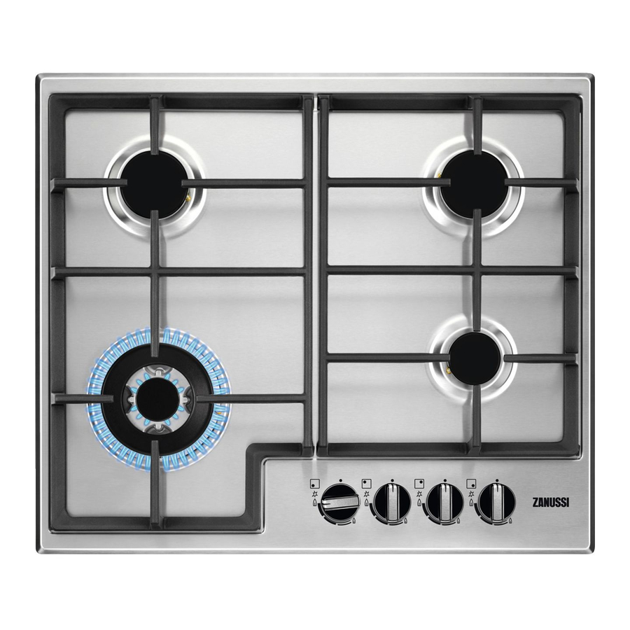
Zanussi Hobs Operating And Installation Manual - Page 8
Browse online or download pdf Operating And Installation Manual for Hob Zanussi Hobs. Zanussi Hobs 15 pages. Gas hobs
Also for Zanussi Hobs: Instruction Booklet (12 pages), Operating And Installation Manual (7 pages), Instruction Booklet (16 pages)

ELECTRICAL
CONNECTION
The appliance is predisposed to function with a
230V monophase voltage tension. Connection
must be carried out in conformity with the
regulations and dispositions of the laws in force.
Before connecting ensure that:
- The limiter valve and the electrical mains can
support the voltage of the appliance (see
registration plate).
- The power supply is correctly earthed according
to the regulations in force.
- The plug or omnipolar interrupter used can be
easily reached once the appliance has been
installed.
Fit the cable with a plug suitable to the voltage
and connect to an appropriate security socket.
If a direct connection to the mains is required, an
omnipolar interrupter with a minimum opening of
3mm between contacts, dimensioned to the
voltage and corresponding to the regulations in
force, should be interposed between the appliance
and the supply. The yellow/green earth cable must
not be interrupted by the interrupter. The brown
coloured phase cable (situated at terminal "L" of
the terminal box) must always be connected to the
network phase. The voltage cable must always be
positioned in such a manner that it at no point
reaches a temperature of 50 C above room
temperature. An example of the best routing is
shown in fig. 3. The cable is guided by use of
clamps fixed laterally to the unit in such a way as
to avoid any contact with the appliance under the
hob.
FO 0073-EN
Fig. 4
YES
CLAMPS
Openings
{
in the
Forniture
Unit
REAR VIEW
NO
REAR VIEW
FO 0238-EN
In case of substitution of the voltage cable use
cable type H05 RRF having a section suited to the
charge, it is furthermore necessary that the
yellow/green earth wire be approximately 2cm
longer than the phase and neutral wires (Fig. 4).
After connection try out the heating elements
allowing them to function for approximately 3
minutes.
The manufacturer declines all responsibility
in case the prevention of accidents regulations
are not respected.
RIGID METALLIC TUBE
OR FLEXIBLE STAINLESS
STEEL TUBE
Fig. 3
9
