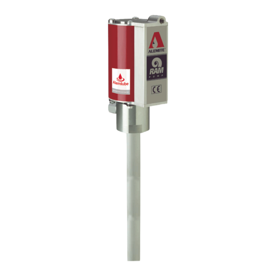
Alemite 9911-R1 Service Manual - Page 10
Browse online or download pdf Service Manual for Water Pump Alemite 9911-R1. Alemite 9911-R1 12 pages. High-pressure stripped pump
Also for Alemite 9911-R1: Service Manual (12 pages), Owners Service Manual (16 pages)

High-Pressure Stripped Pump
Primer Disk to the Primer Rod.
18. Screw Primer Body (37) [with Loctite 222] into the
Lower Tube.
• Follow the thread sealant manufacturer's
recommendations.
• Do not tighten at this time.
CAUTION
Install the Rod and Tube assembly into the Body
with a twisting motion. Use care not to damage
the Seals.
19. Install the Rod and Tube assembly into the Body and
at the same time screw the Upper Tube [with Loctite
222] into the Body.
• Follow the thread sealant manufacturer's
recommendations.
20. Tighten all the threaded pump tube components into
one another.
• Place a bar or other suitable tool in the holes of the
Primer Body for leverage.
• Tighten sufficiently to properly crush all Gaskets.
21. Install O-Ring (8) onto the upper groove of Body
(10).
Air Piston
CAUTION
Use care not to switch Washers (3 and 7). Com-
ponent damage can occur.
22. Install Washer (7) [brass color] and O-Ring (6) onto
the Rod.
23. Install Quad-Ring (5) onto Air Piston (4).
24. Place the Air Piston (observe THIS SIDE UP) on top
of the Rod.
25. Install Washer (3) [silver color] and Nut (2) that
secures the Air Piston to the Rod.
• Tighten the Nut securely.
NOTE: Place an appropriate size punch or
other suitable tool into the hole of the Rod.
See Figure 2-A.
Alemite Corporation
Attach Air Motor to Pump Tube
IMPORTANT: The Air Motor Assembly must
be secured with at least one Carriage Bolt (1a)
and Flange Nut (1b) [preferably at the front].
26. Clamp the Body of the pump securely in a soft-jaw vise.
CAUTION
Install the RAM Air Motor Assembly with care. Dam-
age to Quad-Ring (5) and/or O-Ring (8) can occur.
HINT: Angle the Air Motor Assembly onto
the Quad-Ring and press the exposed portion
into Air Piston (4) with your thumb or finger.
27. Install and seat the Air Motor Assembly onto Body (10).
• Make sure the outlet of the Body orients properly with
the inlet of the Air Motor.
28. Attach the Air Motor Assembly to the Body of the pump
tube with Keepers (11), Carriage Bolts, and Flange Nuts.
CAUTION
Do not overtighten Flange Nuts (1b). Component
damage can occur.
29. Torque the Flange Nuts in a crisscross pattern from 60 to
70 inch-pounds (6.8 - 7.9 Nm).
10
SER 9911-1
Revision (4-02)
