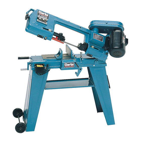
Clarke Metalworker CBS45MD Operating & Maintenance Manual - Page 10
Browse online or download pdf Operating & Maintenance Manual for Saw Clarke Metalworker CBS45MD. Clarke Metalworker CBS45MD 19 pages. 6” (152mm) bandsaw

with the smallest diameter inwards, and the gearbox pulley with the
smallest diameter outwards (as illustrated in the Parts Diagram).
Locate the gearbox pulley on to its shaft, ensuring the grub screw lines up
with the flat on the shaft. Tighten the grub screw fully. Fit the motor pulley
to its shaft so that it lines up with the gearbox pulley. This may be done with
a straight edge across the top of the pulleys to ensure the grooves are in
line. When correctly aligned, tighten the grub screw provided.
Note that the motor pivots about its mountings. To fit the drive belt, lift the
motor and slip the belt over the pulleys. Belt tension is effected by means
of a bolt through the motor mounting plate. Screw the bolt "in" until the
belt can be depressed by approx. ½" at the centre of its run. Lock the
adjusting bolt using the locknut provided.
IMPORTANT. Do not overtighten the adjusting bolt as this will distort the
motor mounting plate.
3. Main ON/OFF Switch Assembly.
On the left end of the machine (looking at the motor side), is the main ON/
OFF switch assembly, which is hanging freely at this stage. Two wires
extend from the back of the assembly, both of which should be earthed
securely to the main body, using the screw and star washer provided,
which is located directly behind the switch assembly (when it is mounted).
Once the wires are securely earthed, the assembly can be mounted using
the two screws provided.
4. Work Stop Assembly.
A work stop is provided, which is used to allow stock pieces of equal length
to be cut without having to measure each piece individually. It comprises
two parts, the work stop, and the mounting rod.
Push the rod into the hole in the edge of the vise, and secure with the
grubscrew provided.
Mount the Work Stop on to the rod, with the flat face towards the saw blade,
and temporarily secure with the grubscrew supplied, ensuring it is not pushed
on too far, as it may interfere with the saw blade when it is lowered.
5. Miscellaneous
A handle (item N) is provided at the right end of the machine, connected
to the right leg (item R). When the machine is lifted using this handle, it will
automatically pivot on to the wheels, mounted on the bottom of the left
leg, allowing the machine to be manouvered easily and quickly around a
workshop. The handle and wheel assemblies are attached as follows.
(Item I)
(Item J)
10
