Clarke Metalworker CBS45MD Operating & Maintenance Manual - Page 11
Browse online or download pdf Operating & Maintenance Manual for Saw Clarke Metalworker CBS45MD. Clarke Metalworker CBS45MD 19 pages. 6” (152mm) bandsaw

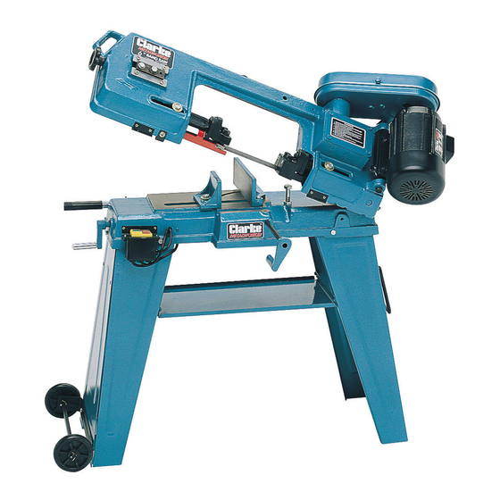
Thread the ends of the handle through the corresponding holes in the right
leg, and locate on the inside of the leg using the split pins provided.
The wheel assembly comprises a bracket, axle and wheels.
Attach the bracket to the base of the left leg using the nuts and bolts
supplied. Thread the axle through the holes at the ends of the bracket, and
insert the split pins in the holes provided in the axle, which will prevent any
lateral movement. Mount the wheels at each end of the axle, and locate by
inserting the split pins provided in the holes at the ends of the axle.
Finally, carry out a thorough check to ensure that all parts are completely
secure and properly assembled.
Maintenance And Adjustments
1. BLADE GUIDE BEARING ADJUSTMENT
This Is the most Important adjustment on your saw. It is impossible to get satisfactory
work from your saw If the blade guides are not properly adjusted. The blade
guide bearings for your Metal culling Bandsaw are adjusted and power tested
with several test cuts before leaving the factory to ensure proper setting.
The need for adjustment should rarely occur when the saw is used properly. If
the guides do get out of adjustment, It is extremely Important to readjust
immediately. If proper adjustment is not maintained, the blade will not cut straight
and if the situation Is not corrected, it win cause blade damage.
Because guide adjustment is a critical factor In the performance of your saw, it
Is always best to try new blade to see if this will correct poor cutting before
beginning to adjust the bearings.
If a blade becomes dull on one side rather than the other for example, it will
begin cuttinhg crooked. A simple blade change should correct this problem -
the more difficult guide adjustment will not.
It a new blade does not correct the problem, check the blade guides for proper spacing.
There should be 0.001" clearance between the 0.025" thickness blade and guide
bearings.
To obtain this clearance adjust as follows:
1.
The inner guide bearing is fixed and cannot be adjusted.
2.
The outer guide bearing is mounted to an eccentric bolt and con be adjusted.
3.
Loosen the nut whilst holding the bolt head with a spanner.
4.
Position the eccentric by turning the bolt to the desired position of clearance.
5.
Tighten the nut.
6.
Adjust the second blade guide bearing in the same manner.
7.
The back edge of the blade should just touch the lip of the Blade Guide bearing.
11
