Blagdon Powersafe Series Quick Start Manual - Page 6
Browse online or download pdf Quick Start Manual for Switch Blagdon Powersafe Series. Blagdon Powersafe Series 8 pages. Power switch box 2/3/4/5 way

3.
Remove the rubber seal from the cable gland and thread it over the cable of the appliance to
be fitted. At this stage leave the gland cover and rubber seal loose on the cable.
4.
Remove the central circuit board locating screw that locates the circuit board and store in a
safe place.
5.
Unclip and remove the circuit board, placing it on a clean dry surface.
6.
Undo (slacken) the two screws that locate the cable clamp and insert the cable through the
cable clamp. At this stage leave the cable clamp loose.
7.
Undo (slacken) the three screws on the cable block to be connected.
8. IMPORTANT: Please also see diagram cable preparation for correct identification of earth,
neutral and live cables.
• Insert the Yellow/green (E) Earth cable and secure with the cable block screw.
• Insert the Blue (N) Neutral cable and secure with the cable block screw.
• Insert the Brown (L) Live cable and secure with the cable block screw.
• Double insulated appliances do not have a earth cable.
Now repeat this process for all the appliances to be connected at this time.
9.
When the mains input and ALL the appliances to be connected have been connected and are
in place, replace the circuit board into the Switch box (gently pulling the cables through the
gland) and secure with the central circuit board locating screw.
10.
The cable clamps can now be secured with the two screws to ensure there is no wiring
movement.
11.
Insert the rubber seal that was previously threaded onto the cable into the seal grip on the cable
gland. (see cable gland sealing diagram)
12.
Screw and hand tighten the cable gland cover that was previously threaded onto the cable to
the cable gland.
Now repeat this process for all the appliances to be fitted at this time.
13.
Ensuring that the recessed Switch box cover seal is located, place the cover onto the box and
secure with the four screws at the back of the box.
14.
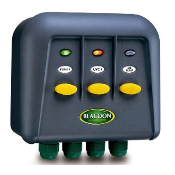
Identify the appliances installed with the labels provided in the recess above the relevant switch
to enable clear identification when the box is in use.
15.
The unit can now be placed on the fixing bracket provided by sliding the box vertically down
onto the bracket.
See power status indicator lights diagram page 2 for status of the Switch box when the
power is supplied to the unit.
6
INSTALLATION
