esera automation 11336 User Manual - Page 4
Browse online or download pdf User Manual for Gateway esera automation 11336. esera automation 11336 9 pages. W/auto-e-connect

9
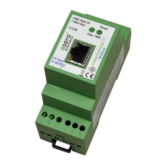
Wiring diagramm
Module topside (1-Wire Bus)
7 = Ground 1-Wire
8 = 1-Wire Data
9 = + 5 V Output
Module bottom side
(supply voltage 9 – 30 VDC)
1 = Negative supply voltage
2 = Positive supply voltage
Connection – Example with multisensory
10
All rights reserved. Reproduction as well as electronic duplication of this user guide, complete or in part, requires the written consent of
ESERA GmbH. Errors and technical modification subject to change. ESERA GmbH, ESERA-Automation 2020
www.esera.de
11336 V2.0 R1.0 Manual
Page 4 of 9
