Doepke Dupline DSS 4R-EIB Operating Instructions Manual - Page 9
Browse online or download pdf Operating Instructions Manual for Accessories Doepke Dupline DSS 4R-EIB. Doepke Dupline DSS 4R-EIB 12 pages. Operating signal sensors with acknowledgement feature

Doepke
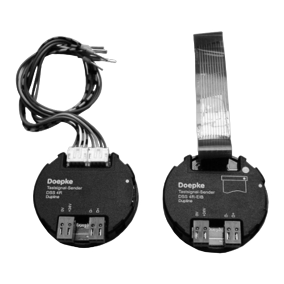
8.3. Connection of EIB Push-buttons to DSS 4R-EIB
The connection between the DSS 4R and a 2-way EIB operating switch is via the 10-
pole flexible circuit-board supplied complete with system plug connectors and the
mounting plate provided. To connect, insert the DSS 4R with connected Dupline line,
power supply and system cable into the flush-mounted socket, pass the system cable
through the mounting plate as illustrated below and connect the EIB switch. When the
mounting plate is screwed down the EIB switch can be snapped into the plate. The con-
nection diagram for the DSS 4R-EIB is shown in Chapter 11.2 on page 12.
Dupline bus /
Supply
voltage
9. Guarantee
All professionally installed, unaltered devices are covered by warranty during the statu-
tory guarantee period from the day of purchase by the end user. The guarantee is not
applicable to damage incurred during transport or caused by short-circuit or overload-
ing. In the event of defects in workmanship or material, which are discovered within the
guarantee period, the company will provide a replacement free of charge. The guaran-
tee will be rendered null and void if the sensing chamber is opened or the device is tam-
pered with.
10. Technical Data
Dupline
Current input
Input channels 4 operating signal inputs
Output channels 2 acknowledgement outputs
Inputs
Power supply not applicable
3931176/08/12/D - The right to make technical changes reserved!
Min.
Type Semiconductor inputs
Voltage
21.5 VDC
EIB mounting plate
EIB switch
System cable
Typ.
750 µA
24 VDC
26.5 VDC
Max.
9
