FLOJET 2100-750 Specificaties - Pagina 2
Blader online of download pdf Specificaties voor {categorie_naam} FLOJET 2100-750. FLOJET 2100-750 4 pagina's. 2100 series duplex diaphragm design automatic water system pump & shower drain • general purpose pump
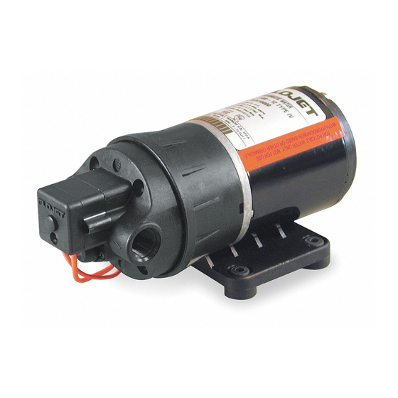
AUTOMATIC WATER SYSTEM INSTALLATION
INSTALLATION
STEP 1
Remove shipping plugs from pump ports. Some water
from factory testing may spill out.
STEP 2
Install inlet A and discharge B port connectors.
STEP 3
Insert rubber mounting grommets onto base plate.
STEP 4
Mount pump vertically, with pump head down or
horizontally in an accessible location. Do not compress
grommets.
WIRING
In an easily accessible location, install a switch to
control electricity to the pump. Turn the pump off when
not in use for extended periods, or when tank is out of
water.
A 7 amp. fuse should be installed in the positive line with
the pump being its only load. (24V model, use 5A fuse).
Red (+)
Fuse
SHOWER DRAIN INSTALLATION
Model 2100-694
STEP 5
Use 1/2" or 3/8" I.D. flexible hose (preferably braided or
reinforced). Use hose clamps on the slip-on barb hose
connectors.
STEP 6
Install no less than 3/8" I.D. hose for feed lines to
fixtures. Use high pressure hose on all city water lines.
STEP 7
Install a Flojet strainer in an accessible location (for
inspection and cleaning) between the tank and pump
inlet. This strainer or equivalent is required for pump
warranty to be valid.
Black (–)
(+)
Switch
Wire size based on total wire length.
0 - 20 ft.
20 - 50 ft.
50 - 80 ft.
A
B
Flojet Shower
Drain Pump
Install Strainer
Inlet Side Only
(–)
Battery
#16 AWG
#14 AWG
#12 AWG