DROPSA 1525730 Gebruikers- en onderhoudshandleiding - Pagina 3
Blader online of download pdf Gebruikers- en onderhoudshandleiding voor {categorie_naam} DROPSA 1525730. DROPSA 1525730 8 pagina's. Volumetric flow meter for controlling the flow of liquids

5. COMPONENTS
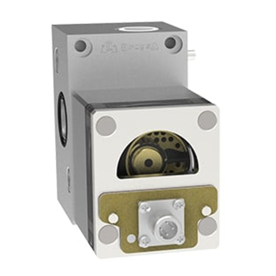
METER PARTS
1
Base
2
Metering module
3
Optical sensor
4
Flow rate adjustment screw
5
By-pass Valve
6. UNPACKING AND INSTALLATION
6.1 UNPACKING
Once a suitable location has been found to install the unit remove the machine from the packaging. Check the device has not
been damaged during transportation or storage. No particular disposal procedures are necessary, as packaging materials are not
dangerous or polluting.
6.2 INSTALLING
Install the flow meter on a proper support surface, free from impediments which could interfere with machine well functioning.
WARNING: All the electric, electronic components, reservoirs and base structure must be grounded.
Connect inlet tubes par.11.3, Figure 1, pos. J) and oil output (par.11.3, Figure 1, pos. K).
-
Connect the sensor wires to terminal board of the electronic control device (cable available as an accessory).
-
Pin 3
To assemble flow meters in batteries, follow the instructions below:
1) Unscrew the two grub screws (par. 11.3, fig.1, pos.1) of the next flow meter.
2) Tighten the two screws (par. 11.3, fig.1, pos.2) to the previous flow meter. Pay attention to the O-Ring correct position to
prevent damages during assembling.
3) Screw again the grub screws (par. 11.3, fig.1, pos.1) to the previous flow meter.
The above operations must be carried out for all the flow meters being assembled.
4
5
Pin 2
Pin 1
Pin 4
3
CONNECTOR (M12X1)
PIN
DESCRIPION
1
2
3
NPN signal
4
PNP signal
2
1
V +
V -
3
