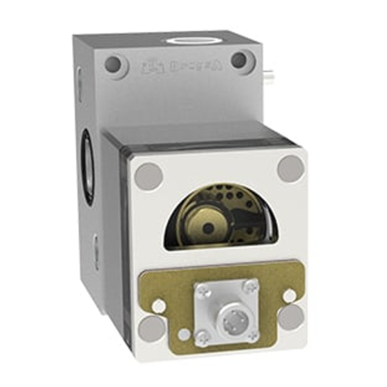
DROPSA 1525730 Gebruikers- en onderhoudshandleiding - Pagina 4
Blader online of download pdf Gebruikers- en onderhoudshandleiding voor {categorie_naam} DROPSA 1525730. DROPSA 1525730 8 pagina's. Volumetric flow meter for controlling the flow of liquids

6.3 TECHNICAL INDICATIONS
It is recommended to use:
Structural steel piping of proper dimensions with check valve
-
Grip-ring pipe fittings (To assembly: block pipe fittings and tighten pipes using a vice)
-
An inlet filter with a proper filter grade (not over 90µ), Dropsa part N°3130309
-
If the machine is operated for the first time:
Decrease oil pumping unit pressure and ensure that all the connections are correct and there are no leaks.
Increase pressure progressively to suit individual flow requirements.
7. PUMP OPERATIONS
Output of FLOWMASTER is easy adjusted using the adjustment needle (par.11.3, fig.1, pos. X).
In event of replacement of the flow satellite module, it is possible divert the flow directly to the output, isolating the module by
activating the flow by-pass valve (optional - par.11.3, fig.1, pos. Y).
8. TROUBLESHOOTING
The following diagnostic table indicates the main anomalies, which may be encountered, the probable causes and possible
solutions.
If you cannot solve the problem, do not attempt to disassemble parts of the machine but contact the Engineering Department of
DROPSA S.p.A., pointing out anomaly details.
ANOMALY
No signal transmitted by
the flow meter
Blocked satellite
Abnormal satellite rotation
Oil leakage
9. MAINTENANCE PROCEDURE
FLOW MASTER has been designed and constructed to require a minimum of maintenance.
For an easy maintenance, it is advised to assemble the machine in an adequate location.
To facilitate maintenance tasks without interrupting the operation of the machine, it is recommended to provide the flow
-
meter with an input ball valve to disconnect parts of the system.
Periodically check pipe-joints to detect possible leaks.
-
Always keep the machine unit clear to readily detect possible leaks.
-
Periodically (once a year or when required) replace the refilling filter, part n°: 3130139.
-
The machine does not require any special tool for check or maintenance tasks. However, it is recommended the use only of
appropriate and good quality tooling, protective equipment (gloves) and clothing (626/94 and DPR 547/55) to avoid injury to
persons or damage to machine parts.
WARNING: Before any maintenance procedure, be sure that power, hydraulic and pneumatic supplies are off
10. DISPOSAL
During maintenance or disposal of the machine care should be taken to properly dispose of environmentally sensitive items.
Refer to local regulations in force in your area.
When disposing of this unit, it is important to ensure that the identification label and all the other relative documents are also
destroyed.
4
PROBABLE CAUSE
• Wrong electrical connection
• Impure oil in the circuit
• Cold oil in the circuit
• Low pressure
• Worn O-ring seals
SOLUTION
→
Check sensors (and motor, for the motorized option)
electrical connections on the control equipment terminal
strips
→
Check and clean the oil output circuit filtering cartridges.
Replace them, if necessary
→
Switch on the pumping system electrical resistance
→
Increase pressure
→
Replace the seals. (see machine parts drawing, par. 11.3)
