anytronics Anyscene 1 Installatie- en bedieningshandleiding - Pagina 2
Blader online of download pdf Installatie- en bedieningshandleiding voor {categorie_naam} anytronics Anyscene 1. anytronics Anyscene 1 6 pagina's. Memory unit

1. Overview and Operation
The Anyscene 1 memory unit provides seven programmable DMX scenes of 36 channels,
plus a 'Blackout' function in a double pattress housing suitable for use in architectural
applications. Only a single Anyscene 1 can be used within an installation and if control at
multiple locations is required the installer should use the Anyscene 512 range.
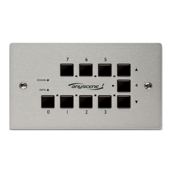
The front panel has ten buttons and ten LED indicators. Switches labelled 1-7 have their
own blue mimic LEDs and are used for storing and recalling the contents of the 7
programmable memories.
The Up and Down buttons are normally used to control the Master level, allowing control
of the overall lighting level.
The green power LED shows when the unit is powered up, and the yellow data LED
indicates that the unit is receiving suitable data from a DMX source for programming or
the unit has gone into standby mode allowing external control. Switch 0 is the blackout
switch and when enabled the corresponding red LED will flash to indicate the unit is in this
mode.
The RJ45 sockets are on the back of the PCB along various option DIL switches and the
connectors for the external scene recall control.
2. Unit Mounting
The Anyscene 1 should be mounted using UK double pattresses with an approximate
depth of 32 mm.
Units 5 & 6 Hillside Industrial Estate
London Road, Horndean,
Hampshire, PO8 0BL
Tel +44 (0)23 9259 9410
Fax +44(0)23 9259 8723
Page 2 of 6
AT1042 Issue 1
Anyscene 1 Operating
Instructions
