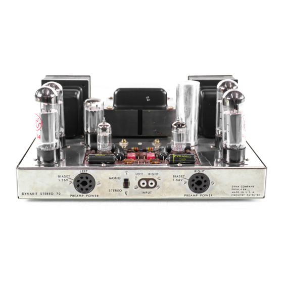
DYNACO Stereo 70 Instructies voor montage - Pagina 7
Blader online of download pdf Instructies voor montage voor {categorie_naam} DYNACO Stereo 70. DYNACO Stereo 70 16 pagina's. Series ii tube amplifier
Ook voor DYNACO Stereo 70: Restauratie Handboek (20 pagina's), Restauratie Handboek (5 pagina's), Gebruikershandleiding (12 pagina's)

37
(-1
Strip both ends of a 5" wire 1/2".
Feed
one end through pin
#8 (8)
and connect it to
pin
#1
of V7 (8).
Feed the other end
through pin
#1 (8)
of V6 and connect to pin
#8
of V6.
38 (v) Connect one end of a 4-1/2" wire to pin #8
of V6
(8).
Connect the other end to pin
#8
of the right power takeoff socket
(8).
39
(I/j
Connect one end of a 1000 ohm (brown-
black-red) resistor to pin #5 of V2 (8).
Connect the other end to pin #6. Repeat for
V3, V6 and V7.
Keep the resistor pigtails
short (about 1/2") for all four of these
resistors.
40
(0{
Mount the printed circuit board PC -3 from
the bottom of the chassis. Note the num-
bers of the eyelets are upright when look-
ing from the rear of the chassis.
Use a
4/40 screw, lockwasher and nut at each
mounting hole.
The two wires from the
board s h a u I d be straightened carefully.
These are used at a later step.
In
making solder connections to the printed
circuit board, all connections are made to
the numbered eyelets in the board. In this
way, there is no danger of damaging the
printed wiring or the components which are
part of the board as sembly. These eyelets
already have solder in them and it is very
easy to make sol de r connections to the
board.
The lead wires should have their
ends stripped back about 1/4", and these
stripped ends should be tinned by heating
with a soldering iron and touching against
the solder. When the wire is to be soldered
to the eyelet on the board, the eyelet is
heated until the solder flows; and then the
wire end is pushed into the eyelet and held
in place until the solder sets. This type of
soldering can be done with a very small
iron, and it is preferable not to use any
more heat on the eyelet on the board than
is required to get the solder to flow.
41 (~Connect a 2-3/4" wire from eyelet #23 (8)
of the printed circuit board to pin
#6
of
V6
(8) .
42
('-1
Connect a
3"
wire from eyelet
U22 (8)
to
pin
tl6
of V7 (8).
43
(0
Connect a 3" wire from eyelet #19 (8) to
filter capacitor lug # 3.
44
(tI)
Cut the leads of a 22,000 ohm (red-red-
orange) res isto!' to 1".
Connect one end of
the resistor to capacitor lug' #3 (8).
Con-
nect the other end to capacitor
lug 114.
45
(0
Connect a 3-1/2" wire from eyelet #20 (8)
to capacitor lug #4
(8).
46
("1
Observe two wires extending from the
printed circuit board just under the input
socket. Connect the extended wire on the
right to the ground (short) lug of the right
input socket.
Con n e c t the left extended
wire to the ground (short) lug of the left
input socket.
47
(V)
Connect a 1-1/2" wire from eyelet #18 (8)
to lug #5 of the right power takeoff socket
(8) .
48
(0
Twist together a pair of 3-1/4" wires.
Connect one pair of ends to eyelets # 15 (8)
and #16 (8).
Connect the other ends to pins
#1
(8) and #2 (8) of the right power takeoff
socket.
49
(v')
Connect one end of a 10 ohm (brown-black-
black) resistor from eyelet
#10 (8)
to pin
#3 of the right power takeoff socket (8).
50
("1
Connect one end of a 2-1/2" wire to eyelet
# 21 (8). Connect the other end to lug # 2 of
the right potentiometer
(8).
51
('"1
Connect one end of a 5-1/2" wire to eyelet
#14 (8), and connect the other end to pin #4
of V6
(8).
52
(0
Connect a 2" wire from lug #3 of the input
switch
(8)
to the long lug of the right input
socket.
53 ({/) Connect one end of a 470,000 ohm (yellow-
violet-yellow) resistor to
long
lug of right
input socket.
Connect the other end to the
ground (short) lug of the right input socket
(8) .
54
(£11
Connect one end of a 470,000 ohm (yellow-
violet-yellow) resistor to lug # 1 of the input
switch
(8).
Connect the other end to the
ground short lug of the left input socket
(8).
55
(0
Connect one end of a 1-3/4" wire to eyelet
#
17 (8).
Connect the other end to the long
lug of the right input socket
(8).
56
(/.-1
Connect one end of a 3-1/2" wire to eyelet
#7 (8).
Connect the other end to the long
lug of the left input socket.
57
(0
Connect a short link of wire from the left
input socket long lug (8) to lug 4i 2 of the
input switch (8).
58
(0
Connect a 1-1/4" wire from eye let # 3 (8) to
pin 115 of the left takeoff socket (8).
5
