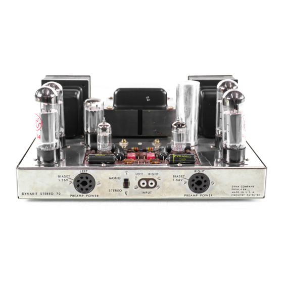
DYNACO Stereo 70 Instructies voor montage - Pagina 9
Blader online of download pdf Instructies voor montage voor {categorie_naam} DYNACO Stereo 70. DYNACO Stereo 70 16 pagina's. Series ii tube amplifier
Ook voor DYNACO Stereo 70: Restauratie Handboek (20 pagina's), Restauratie Handboek (5 pagina's), Gebruikershandleiding (12 pagina's)

should touch the c has sis.
P lug in the GZ -34
rectifier tube, and in about 10 seconds there will
be
a
current flow which will cause a meter deflec-
tion. As the rectifier warms up, the reading will
increase.
The left bias potentiometer should be
adjusted until the meter reading at pin #8 is the
same as across the dry cen (this reading will be
1. 56 volts if the meter is of sufficient accuracy).
This adjustment should then be made using the
right bias potentiometer and measuring the voltage
at pin
118
of the right power takeoff socket.
Then
repeat the setting for the left control and left set
of tubes. There may be Some drifting of the read-
ing as the tubes heat, but this will stabilize within
15 minutes after which no further adjustment is
required.
Small variations will occur with line
voltage changes.
These will have no effect on
performance.
A
It h
au
g
h the setting
is
a semi-
permanent one, at times of tube replacement or
similar repair or maintenance work, resetti.ng of
the bias will preserve peak performance and keep
distortion at an absolute minimum.
If in the course of bias setting it is found that
the control range of the potentiometer is insuffi-
cient to obtain the correct setting, do not operate
the amplifier until the cause of the difficulty has
been established.
Operation with incorrect bias
can lead to damage to the output tubes and/or other
components.
Note that the use of pin #8 as directed in the
wiring instructions means that this pin cannot be
used as a connection point for preamplifiers if the
preamplifiers take power from the power takeoff
sockets of the front panel.
Most preamplifiers do
not require the use of this pin. However, for those
which do, some other pin must be used as a bias
check point.
If no other pin is available,
the
connection from pins
1/8
of V3 and V6 to the pre-
amplifier power sockets must be omitted; and bias
measurements should be based on voltages read
directly at pin #8 of V2 or V3 for the left channel
or pin 1i8 of V6 or V7 for the right channel.
PREAMPLIFIERS
The Dynakit Stereo 70 can be used with any
conventional stereo or monophonic preamplifier,
or pair of monophonic preamplifiers.
Preamp-
lifiers which con t a i n their own built-in power
supply can be used by connecting their audio cables
to the input socket.
Those units which require
power from the amplifier can be readily used with
the Dynakit provided that the power sockets on the
front panel of the Dynakit are properly wired. The
preceding instructions include the proper wiring
for both Dynakit and Heathkit WA-P2 preamplifiers
so that these can be inserted without modification.
Should others requiring different socket connec-
lions be used, the socket wiring can be changed to
suit their requirements.
PROTECTIVE COVER
The protective cover which
is
supplied with the
Stereo 70 has been designed to be both functional
and good looking.
It
should be used on the amplifier
if the amplifier is located where it can be inadver-
tently to u c h e d by anybody.
There is voltage
appearing above chassis on the printed circuit
board which is not lethal, but which can give an
uncomfortable shock.
In
addition, the tubes get
hot in normal operation, and touching them can
result in a minor burn. Therefore, the protective
cover should generally be used.
The amplifier should be located where there is
adequate ventilation - at least one foot of space
above
it
and a few inches all around. The amplifier
can be located away from other elements of the
high fidelity system so there should be no need to
put it in too confined a space.
NEVER put anything
on top of the cover which can obstruct air flow.
Always use the amplifier with the tubes in vertical
position.
The cover and bottom plate arc affixed at the
same time. The amplifier chassis should be set
over the bottom plate, the cover lowered over the
chassis, and then the three pieces are fastened
together with the
six
sheet metal sc rews through
the chassis sides.
USING THE STEREO 70
The Dynakit Stereo 70 is designed to be used in
any of three different modes of operation: stereo-
phonic use in which separate stereo channels are
carried through the two sides of the amplifier;
high-low frequency amplification where one chan-
nel carries the low frequencies and the other the
high frequencies with a frequency dividing network
ahead of the amplifier; and monophonic use with
the two channels paralleled so that 70 watts of
power are available.
In
stereo use, the stereo 70 provides 35 watts
per channel.
A stereo preamplifier's two output
cables, or other left and right signals, are con-
nected to the input jacks of the ste reo 70. The
input switch is set to "stereo", and remains in that
pos ition whenever two input cables are connected,
allowing the preamplifier to do all the switching.
The right loudspeaker is connected to the "right"
screw terminal strip between the
"c"
terminal and
the terminal corresponding to the speaker's im-
pedance.
The left loudspeaker is similarly con-
nected to the "left" terminal strip.
If there are two monophonic preamplifiers
which require power from the amplifier, each is
connected to the respective preamplifier power
takeoff socket.
As provided, these will accom-
7
