JADO 853/451 Series Installatie-instructies - Pagina 2
Blader online of download pdf Installatie-instructies voor {categorie_naam} JADO 853/451 Series. JADO 853/451 Series 4 pagina's. Pressure balanced shower set pressure balanced shower set with check stops and trim
RECOMMENDED TOOLS
Tubing Cutter
ROUGHING-IN DIMENSIONS
For reference
FINISHED WALL
2-3/8" D.
(60 mm)
4-1/4"
(109 mm)
6-11/16" to 8-1/4" REF.
(170 to 210 mm)
74" FOR HEAD
CLEARANCE
(OPTIONAL)
(1880 mm)
"SEE ILLUSTRATION"
CRYSTAL
STRAIGHT
CROSS
LEVER
LEVER
HANDLE
HANDLE
HANDLE
BOTTOM OF
OR SHOWER
48" TO 54"
OPTIONAL
(1219 mm TO 1372 mm)
INLETS 1/2" NPT
OUTLETS 1/2" NPT
3-3/8"
(86 mm)
THREADED INLETS (STOPS)
2
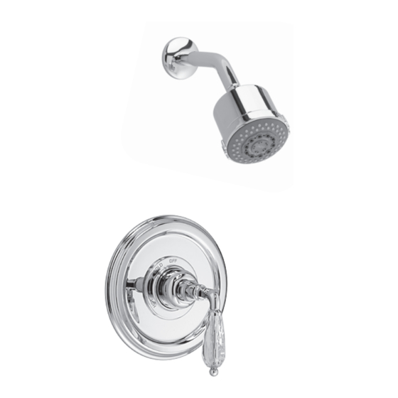
CAUTION: Protect finish on SHOWER ARM
INSTALL TRIM
and SHOWER HEAD when installing.
Push CAP (1) onto VALVE CARTRIDGE (2). Secure CAP (1) to
VALVE CARTRIDGE (2) with SCREW (3) for LEVER HANDLE only.
(Spline in CAP (1) must fully engage spline on cartridge stem).
Mount ESCUTCHEON (5) with gasket to valve body and secure
with SCREWS (6).
Push the COVER (7) as shown over the CAP (1) and align
prongs on COVER (7) with screw holes in ESCUTCHEON (5).
Important! Make sure COVER (7) snaps over the SCREWS (6).
Remove PIPE CAPS (8) from shower pipe.
Install SHOWER ARM (9) and SHOWER HEAD (10)
2a
INSTALL HANDLE (ADJUST HOT LIMIT STOP PRIOR
TO HANDLE INSTALLATION, SEE STEP 3)
For Cross Handle: Thread HANDLE BASE (11) onto threads
of CAP (1) until seated against it's internal stop.With VALVE
in off position align CROSS HANDLE (12) as desired. Install
CROSS HANDLE (12) onto VALVE STEM (13) and tighten
HANDLE SCREW (14). Thread INDEX (15) into
CROSS HANDLE.
Lever Handles: Thread HANDLE BASE (16) onto
threads of CAP (1) until seated against it's internal
stop. Install FRICTION WASHER (17) onto base
of LEVER HANDLE (18). Align LEVER HANDLE (18)
and tighten set screw with HEX WRENCH (4)
supplied with faucet to secure handle.
Channel Locks
Adjustable Wrench
1-5/8" TO 3-1/4"
(41 mm TO 82 mm)
1/2" NPT
OPTIONAL TO
FINISHED
FLOOR
USUALLY
BETWEEN
72'' AND 84"
(1829 mm AND 2134 mm)
SHW
7-7/8"
(200 mm)
TUB
1/2" PLUG
TUB
STALL
5-7/8"
(149 mm)
Teflon Tape
1
ROUGHING-IN
CAUTION
NOTE
When soldering, remove PLASTER GUARD, CARTRIDGES and CHECK
STOPS (IF PRESENT). When finished soldering, flush valve body, replace
cartridges, check stops (if present) and plaster guard to continue installation.
Use thread sealant or Teflon tape on threaded connections.
See Roughing-in diagram before starting.
Connections are:
1/2" female NPT for threaded inlets
Connect RISER PIPE (1) to MANIFOLD (2)
top outlet marked "SHR".
Plug TUB outlet with 1/2" NPT PLUG supplied.
For proper positioning the finished wall
must be within side wall of PLASTER GUARD (4).
If the valve is installed on a fiberglass or
other thin wall application, the PLASTER
GUARD (4) can be used as a support.
Cut a 4" dia. hole in the shower stall.
Drill two additional 1" holes to allow
access to the stops.
Remove PLASTER GUARD (4), rotate
180˚ so that indicated screw holes fit
MANIFOLD (2). Push CAP on valve, place
ESCUTCHEON on and attach with screws.
Connect hot and cold water supplies.
Cap off shower pipe (5).
For support, use pipe BRACES (6) secured to wooden braces.
With valve turned off, turn on water supplies. Check for leaks.
7
17
16
4
18
LEVER HANDLES
Plumbers' Putty or Caulking
Turn off water at main supply.
2
HOT
9
10
1
13
5
3
THREADS
ON CAP
6
11
12
14
CROSS HANDLE
15
Phillips Screwdriver
Regular Screwdriver
5
6
1
COLD
4
PLUG
8
2
10 9 4 6 2 D