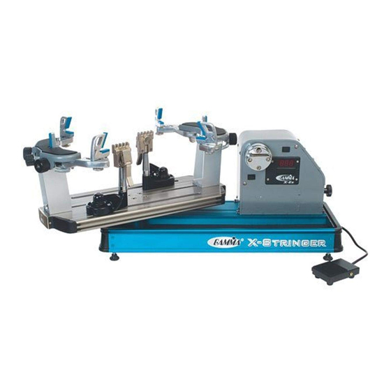
Gamma X-ES Gebruikershandleiding - Pagina 6
Blader online of download pdf Gebruikershandleiding voor {categorie_naam} Gamma X-ES. Gamma X-ES 19 pagina's.

- 1. Table of Contents
- 2. Gamma X-Es Gamma X-Es Gamma X-Es Gamma X-Es
- 3. Features
- 4. Assembly Instructions
- 5. Power Connection & Controls
- 6. Mounting the Frame
- 7. Stringing the Frame
- 8. Additional Features
- 9. Pathfinder Awl
- 10. Maintenance and Adjustments
- 11. Troubleshooting Tips
- 12. Parts List
- 13. Parts Drawing
POWER CONNECTION & CONTROLS
A
F
A
Instructions for Power Connection and Controls
CAUTION ! Before connecting to the power supply, check the voltage supply switch
located on the back side of the tensioner. To change from 110 to 220 volt service
slide the switch fully to the left or to the right until "115V" or "230V" appears on the
switch plate.
The acceptable range of input voltages for the "115 V" setting is between 110 V and 120 V
@ 60 Hz and for the "230 V" setting, between 220 V and 240 V @ 50 to 60 Hz. If you have
any question regarding the input voltage supply for your area, please ask your electric
utility company. When using extension cords, use grounded heavy duty extension cords
rated for 15 AMP service.
To install the power cord, insert the female end of the power cord into the Power Cord
Socket located on the rear panel (letter C). T o connect the foot pedal switch, insert the 2
pin male connector located at the end of the foot pedal switch cord into the two pin
receptacle located on the back pa nel. Tighten the connector with the sleeve nut located on
the foot pedal switch connector .
After checking to be certain that the machine is set for the correct input volt age, switch on
the machine by pressing the Lighted On-Off Power Switch on the rear p anel.
WARNING!
BY ADULTS OR UNDER ADULT SUPERVISION ONLY .
NEVER OPEN UNIT WITH POWER CONNECTED
B
C
E
B
D
FOR INDOOR USE ONLY . TO BE USED
Front Panel Features
A - String Gripper
B - Tension Switch
C - L.E.D. Tension Display
D - Tension Adjustment Knob
E - Calibration Screw Cover Plate
F - Gripper Reversing Switch
D
Side Panel Features
A -
Lighted Power Switch
To turn the power on, press the left
side of the switch.
C
B -
5 Amp Fuse Holder (w/ spare fuse)
C -
A/C Power Cord Socket
D -
2 Pin Foot Pedal Switch Receptacle
5
