Fronius 63A-1 Snelstarthandleiding - Pagina 3
Blader online of download pdf Snelstarthandleiding voor {categorie_naam} Fronius 63A-1. Fronius 63A-1 10 pagina's. Smart meter
Ook voor Fronius 63A-1: Beknopte handleiding (17 pagina's), Beknopte handleiding (20 pagina's), Snelstarthandleiding (2 pagina's), Snelstarthandleiding (2 pagina's), Snelstarthandleiding (8 pagina's)
1 GENERAL
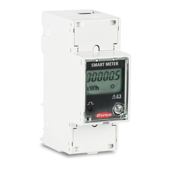
Fronius Smart Meters (single phase or 3-phase) are energy meters that work in conjunction with the Fronius
Datamanager V2. The Smart Meter must be connected to the Fronius Datamanager V2 which comes built-in to
all Fronius SnapINverters (Galvo, Primo, Symo and Eco), and can be retrofitted into all other Fronius inverters.
Using a ModBus RTU / RS 485 connection protocol, the smart meter can be utilised to monitor consumption
data or in order to limit the export of a PV system. They can measure current/voltage/energy/reactive
power/apparent power in total or per line.
Once a battery is added to an installation a Smart Meter is mandatory. If the installation is single or dual phase
a 3-phase Smart Meter can be used.
This document describes how to do install and setup the Fronius Smart Meter.
1.1 Requirements
/ Important! The Fronius Smart Meter cannot be used in combination with the Fronius Datamanager Version 1.
/ The Fronius Datamanager V2 needs to have a software version of V3.3.6-13 or greater. (For details how to
upgrade the firmware see chapter 1.3 Software update of Fronius Datamanager).
/ The Datamanager needs to be set up before executing the meter settings. For information on how to set up
the Fronius Datamanager please see the Fronius inverter or the Fronius Datamanager manual (for Fronius
Galvo/Symo/Primo/Eco):
http://www.fronius.com/cps/rde/xbcr/SID-DBD64F5C-
18F6818F/fronius_australia/42_0426_0191_EA_388899_snapshot.pdf
1.2 Where to put the Fronius Smart Meter
Due to the setup of installations in Australia, in most cases the meter will be put into the feed-in path (diagram
1). If the PV system is connected to a sub board it's most likely to achieve the load measurement by having the
meter in the feed-in path. In rare occasion it can be put into the consumption path (diagram 2).
/
Feed-in point
In this setting the solar generation passes through the meter as well as the site load.
PV System
(c) Fronius Australia Pty. Ltd, 2015
Loads
Loads
(Diagram 1)
Site
Fronius
main
Smart Meter
switch
Grid
3/10