ALLIED MEDICAL Spectrum Healthcare ErgoRaiser Instructies en handleidingen - Pagina 3
Blader online of download pdf Instructies en handleidingen voor {categorie_naam} ALLIED MEDICAL Spectrum Healthcare ErgoRaiser. ALLIED MEDICAL Spectrum Healthcare ErgoRaiser 4 pagina's.

Multiple Configurations - support on a raised surface
Please note:
any raised surface must be designed to support the human load and assessed as providing a safe stable
platform for the required module(s).
Further information, instructions and guidelines
Registered: Safe Working Load in all configurations – 80kg (BS EN 12182:2012.)
The support pad
The ergonomic shaping of the pad in conjunction with the polyurethane foam of which it is made, comfortably cradles the
limb in all positions. The pad may be transferred to whichever surface is to form the support platform for the limb and is
anchored in position by fitting the raised plug on the underside securely into the appropriate socket on the module. Care
must be taken that the pad is securely in position and clean before allowing the limb to rest.
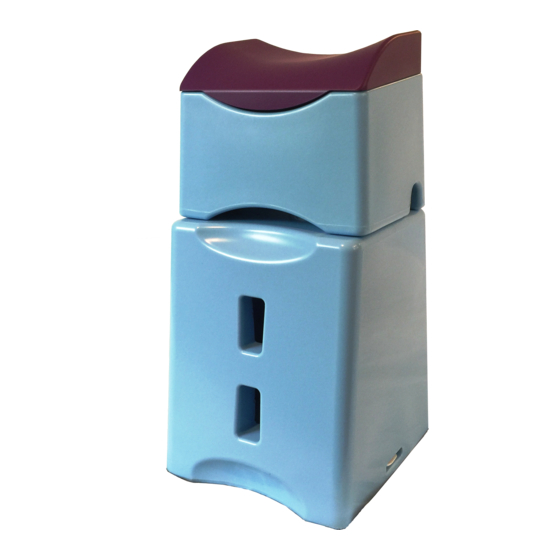
Stowing the top module and pad inside the lower module
To enable stowage, the top module and pad assembly must be correctly orientated and aligned
to match the shape of the cavity. To aid this process the small arch (a) on the side wall of the top
module, should be aligned with the raised guide rail (b) on an inside wall of the cavity. The top
module and pad will then slide into the lower module and can be secured in place by the lid.
When unloading, the small arch provides a finger hold to aid withdrawal of the assembly.
Operating the latch to remove and refit the lid
To open the latch: loosen both knobs on the latch just sufficiently to allow you to slide the
latch bar fully backwards out of its slot (d) on the module. Re-tighten knobs to hold latch
open. Remove lid.
To refit the lid: position the lid shape to match the shape of the cavity. Insert the protruding
tag on the lid edge furthest away from the latch into the corresponding slot (c) on the inner
wall of the module. Press the lid flat to rest against the internal ledge.
To close the latch: loosen the knobs just sufficiently to allow you to slide the latch bar fully
forwards into the adjacent slot (d) on the inner wall of the module. Once latch bar closed
into slot, fully tighten both knobs to ensure security of lid.
There are no hinges on the lid to trap dirt and bacteria; entire latch mechanism may be
dismantled for cleaning.
Dismantling and re-assembling the latch
WARNING – please note:
Before dismantling, note exact position of all component parts (see diag.). Ensure they are placed in same order when
re-assembling; failure to do this will render the latch ineffective.
Dismantling: Release and remove both knobs (1). Remove the latch bar (2). Release
and remove both hex nuts (3). Remove bolts (4).
Re-assembly: Push the bolts (4) through the holes from the underside of the lid. From
the outer side of the lid, thread and wind the hex nuts (3) onto the bolts and fully
tighten. Re-position the latch bar (2) over the bolts, chamfered end uppermost and
facing near outer edge of lid. Re-position top knobs (1) and tighten.
Latch contains small parts; to avoid risk of choking, keep away from small children.
