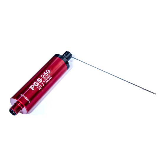
Allora Positive Contact PCS-250 Handleiding voor installatie-instructies - Pagina 6
Blader online of download pdf Handleiding voor installatie-instructies voor {categorie_naam} Allora Positive Contact PCS-250. Allora Positive Contact PCS-250 12 pagina's.

Please Note: Unless otherwise specified when ordered, the TCU-250 Control Unit
has been preset with a CW direction, #2 Time Setting and a HI Rate.
OK LED (
See Relay Control Switches Below)
The OK LED will illuminate at power on. When a start signal
is initiated the LED will momentarily turn off. If a good
condition has been detected the LED will again illuminate.
FAULT LED (
See Relay Control Switches Below)
When a fault or broken tool condition is detected the FAULT
LED will illuminate momentarily or until the unit is reset if the
relay is set to Latch.
TEACH LED and Push Button
After the sensor has been installed you must teach the
system the location of the tool or object to be monitored.
Push the teach button one time, and the teach LED will
illuminate. Push the teach button again and the sensor will
begin its learn cycle. A start signal can also be applied to
begin the learning cycle. The system stores the information
in memory and does not require another learning cycle
when power has been removed.
CW / CCW Switch
This switch selects the desired swing rotation of the sensor.
Time Switches
These switches control the amount of time the sensor rotates during the scanning sequence. Since it takes a
greater amount of time to swing the sensing needle 180º than 90º a greater amount of time needs to be set. If
the sensor will not reach its end or fault position with the tool removed simply set more time. NOTE: If a TIME
selection has not been made the Control Unit operates at a default LO-LO setting used for very small micro-
drill applications only. (See LO/HI Switch settings below with regards to V-seal in Swing Arm Assembly).
LO / HI Switch
Selects the rate at which the sensor swings. "LO" rate is a slower swing rate generally used for micro
tool detection. NOTE: The V-seal in the swing arm assembly provides additional protection against
contaminants and should not be removed in most applications. The V-seal may however restrict the
sensors motion when the swing rate is set on "LO". If your application does not allow "HI" rate
operation, you may remove the V-seal from the swing arm assembly to determine if this solves the
problem.
NT / ET Switch
Selects the tolerance width relative to the taught value. NT = Normal Tolerance ( factory preset )
ET = Extended Tolerance. This feature is used when monitoring multiple tools of different diameter,
primarily on CNC machining centers.
These switches are used to set condition and the operation of the controls internal relays
These feature has been added for increased interface flexibility
FAULT Relay Contact Configuration
NO= Normally open
NC= Normally closed
FAULT Relay Operation
M= Momentary
L= Latch
Sensor Control Unit Switches
Relay Control Switches
NC
L
NC
L
NO
M
NO
M
OK
FAULT
CW
CCW
1
2
TIME
3
LO
HI
NT
ET
OK Relay Contact Configuration
NO= Normally open
NC= Normally closed
OK Relay Operation
M= Momentary
L= Latch
Page 5
TEACH
.
