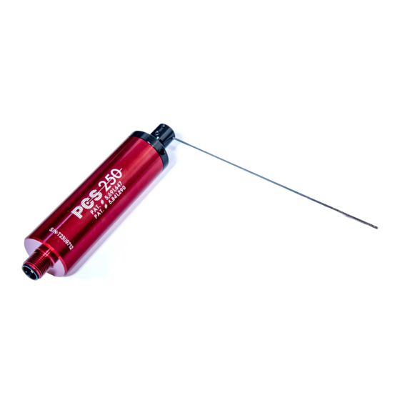
Allora Positive Contact PCS-250 Handleiding voor installatie-instructies - Pagina 8
Blader online of download pdf Handleiding voor installatie-instructies voor {categorie_naam} Allora Positive Contact PCS-250. Allora Positive Contact PCS-250 12 pagina's.

Please refer to the section that best describes the problem you are having.
Determine if you can answer YES to all of the questions. If not, attempt to correct
the condition. If at anytime you have questions, please contact our service
department at 1-855-TOOL-911 (855-866-5911).
SYSTEM FAULT (Red and green lights are illuminated simultaneously.)
• Has a time been selected on the TCU-250?
• Is the PCS-250 connected properly?
• Color coded wires of cable should be attached to the correct terminals on the TCU-250
• Cable should be screwed tight to the PCS-250
• The inside of the PCS-250 connector should be dry
• Manually move the sensing needle away from the start position. Does the sensing needle return to the start
position on its own?
• Is there approximately 4.1VDC across the blue and black terminals on the TCU-250? (The PCS-250 must
remain connected to the TCU-250 for this measurement.)
• Is there 24VDC across the Power terminals on the TCU-250?
• If not, see No Power to TCU-250
TCU-250 WILL NOT START (Lights remain steady, PCS-250 does not swing and TCU-250 gives no output
when a start signal is applied.)
• Is the start signal being applied to the correct terminals?
• Terminals 15 & 16 are for a 24VDC start signal.
• Terminals 14 & 16 are for a 115VAC start signal.
• Is the correct start signal being applied?
• The signal can be AC or DC voltage. Polarity does not matter.
• The TCU-250 can be started with a low, high, low sequence or a high, low, high sequence. The
TCU-250 will always start on the transition from low to high.
• Is the high condition either 24V or 115V?
• Is the low condition 0 V?
• The low condition must be 0 V. If the low condition is not an absolute 0 V, the TCU-250
may not recognize it.
• Is each change in condition being held for at least 100ms?
• In an environment with a lot of electrical noise, (ie: large motors or motor starters), the high, low,
high sequence will block any noise from accidentally starting the TCU-250.
• Is the start signal being applied after the TCU-250 has completely finished its last cycle?
NO OUTPUT FROM TCU-250
• Does the PCS-250 swing when the TCU-250 is given a start signal?
• If not, see TCU-250 Will Not Start
• Is the red or green light illuminated, and at its normal intensity?
• If not, see No Power to TCU-250
• The outputs from the TCU-250 are momentary (500 ms.). Can your application use an output of this
duration?
• The outputs from the TCU-250 can be set to latch. (See Installation Instructions)
• With tool present, give the TCU-250 a start signal. Do contacts 11 & 12 close (or open momentarily
depending on face plate settings)?
• This same tool check can be done for the fault output by removing the tool and checking across
contacts 9 & 10.
PCS-250 System
Trouble Shooting Guide
Page 7
