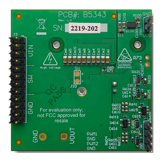
EPC EPC90147 Snelstarthandleiding - Pagina 8
Blader online of download pdf Snelstarthandleiding voor {categorie_naam} EPC EPC90147. EPC EPC90147 14 pagina's.

QUICK START GUIDE
The design of the heat-spreader is shown in figure 10 and can
be made using aluminum or tellurium copper for higher
performance.
The heat-spreader is held in place using countersunk screws
that fasten to the mechanical spacers which will accept M2 x
0.4 mm thread screws such as McMasterCarr 91294A002.
When assembling the heatsink, it may be necessary to add a
thin insulation layer to prevent the heat-spreader from short
circuiting with components that have exposed conductors
such as capacitors and resistors, as shown in figure 11. Note
that the heat-spreader is ground connected by the lower
most mounting post. A rectangular opening in the insulator
must be provided to allow the TIM to be placed over the FETs
to be cooled with a minimum clearance of 1 mm on each side
of the rectangle encompassing the FETs. The TIM will then
be similar in size or slightly smaller than the opening in the
insulator shown by the red dashed outline in figure 11.
EPC recommends Laird P/N: A14692-30, Tgard™ K52 with
thickness of 0.051 mm the for the insulating material.
A TIM is added to improve the interface thermal conductance
between the FETs and the attached heat exchanger. The
choice of TIM needs to consider the following characteristics:
• Mechanical compliance – During the attachment of the
heat spreader, the TIM underneath is compressed from
its original thickness to the vertical gap distance between
the spacers and the FETs. This volume compression exerts
a force on the FETs. A maximum compression of 2:1 is
recommended for maximum thermal performance and to
constrain the mechanical force which maximizes thermal
mechanical reliability.
• Electrical insulation – The backside of the eGaN FET is a
silicon substrate that is connected to source and thus the
upper FET in a half-bridge configuration is connected to the
switch-node. To prevent short-circuiting the switch-node
to the grounded thermal solution, the TIM must be of high
dielectric strength to provide adequate electrical insulation
in addition to its thermal properties.
• Thermal performance – The choice of thermal interface
material will affect the thermal performance of the thermal
solution. Higher thermal conductivity materials is preferred
to provide higher thermal conductance at the interface.
EPC recommends the following thermal interface materials:
• t-Global
P/N: TG-A1780 X 0.5 mm
• t-Global
P/N: TG-A6200 X 0.5 mm
• Bergquist
P/N: GP5000-0.02
• Bergquist
P/N: GPTGP7000ULM-0.020 (conductivity of 7 W/m·K)
NOTE. The EPC90147 development board does not have any current or thermal protection on board. For more information
regarding the thermal performance of EPC eGaN FETs, please consult:
D. Reusch and J. Glaser,
DC-DC Converter Handbook, a supplement to GaN Transistors for Efficient Power Conversion,
First Edition, Power Conversion Publications, 2015.
EPC – POWER CONVERSION TECHNOLOGY LEADER |
A
5.2
Figure 10: Heat-spreader details
5.2
Figure 11: Insulator sheet details with opening for the
TIM with location of the FETs
(highest conductivity of 17.8 W/m·K)
(moderate conductivity of 6.2 W/m·K)
(~0.5 mm with conductivity of 5 W/m·K)
EPC-CO.COM
| ©2022 |
39.0
14.0
17.0
9.2
20.0
39.0
29.2
20.0
9.2
EFFICIENT POWER CONVERSION
EFFICIENT POWER CONVERSION
28.0
EPC90147
8.0
3.6
11.0
M2 screw at heat
countersunk,
Scale 8:1
Units: mm
Part thickness: 1.5 mm
Ø4.6 (x3)
11.0
Units: mm
| 8
