EPC EPC90147 Snelstarthandleiding - Pagina 9
Blader online of download pdf Snelstarthandleiding voor {categorie_naam} EPC EPC90147. EPC EPC90147 14 pagina's.
QUICK START GUIDE
EXPERIMENTAL VALIDATION
The performance of EPC90147 was tested under the operating
conditions given in table 2 unless otherwise specified.
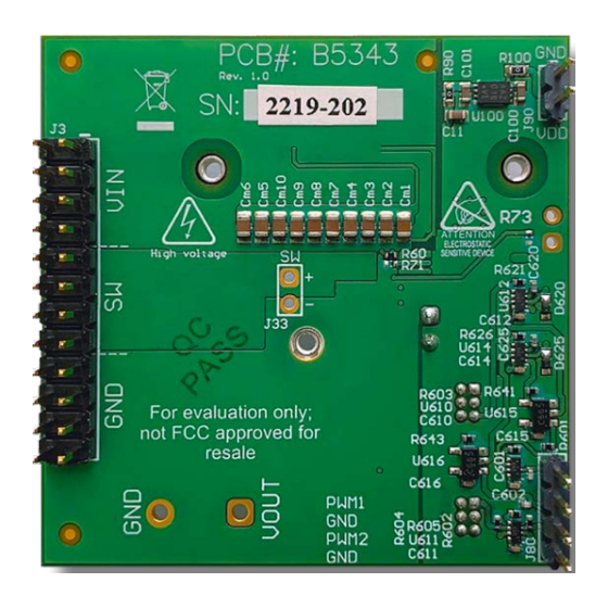
A heat-spreader per figures 10 and 11 with t-Global TG-A1780
thermal interface material (TIM) and a heatsink from Wakefield
Vette 567-24AB using the same TIM was added to the board prior
to testing at high current.
Additional input and output capacitance are added to suppress
input and output voltage ripple at high output current as shown
in Table 2.
ELECTRICAL PERFORMANCE
Measure Waveforms
EPC – POWER CONVERSION TECHNOLOGY LEADER |
Figure 12: Measured inductor current and switch node waveforms when operating from
48 V at 500 kHz and delivering 0 A into a 12 V load
EPC-CO.COM
| ©2022 |
Table 2: Test conditions
Parameter
Regulated Input voltage
Regulated Output voltage
Switching frequency (f
Inductor (mounted on motherboard)
Additional Input capacitance (min.)
Additional Output capacitance (min.)
Maximum case temperature
Dead time
R
(R60) and R
Boot
[1] 2.2 μH inductor from Vishay, P/N IHTH1125KZEB2R2M5A.
[2] Capacitors used:
4.7 μF, 100 V, x5 (P/N: GMC32X7R475K100NT)
[3] Capacitors used:
4.7 μF, 100 V, x5 (P/N: GMC32X7R475K100NT)
47 μF, 80 V, x1 (P/N: 80SXV47M)
5 A/div
10 V/div
500 ns/div
)
1000
S
1500
(R78)
DRV
Inductor
current
Switch
node
10 V/div
10 ns/div
EPC90147
Max
Units
48
V
12
V
500
kHz
2.2
μH
[1]
[2]
23.5
μF
[3]
70.5
μF
110
°C
10
ns
3.3
Ω
| 9