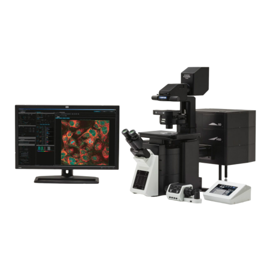
Olympus FV3000 Veiligheidshandboek - Pagina 10
Blader online of download pdf Veiligheidshandboek voor {categorie_naam} Olympus FV3000. Olympus FV3000 16 pagina's.
Ook voor Olympus FV3000: Bedieningshandleiding (38 pagina's), Bedieningshandleiding (5 pagina's)

1× gives a brighter image while making the optical slice thicker, while decreasing the size
of the Airy Disk from 1× gives a darker image while not making the optical slice thinner.
4.5 Using the LSM Imaging Tab
Under Scan Settings tab, in which you can set the parameters for your imaging:
• XY
➢ Type: normally, Galvano is used. For live imaging,
resonant imaging is preferred for its fast imaging
but resolution will be lower.
➢ Mode: Normally, mono-directional mode is used.
For fast imaging, roundtrip can be selected where
phase correction has to be adjusted.
➢ Interlace: Normally OFF is preferred. If 2x is
selected, it would capture the image by skipping
every 2 lines of the image.
➢ Speed: the slower, the better your image will be
(a higher signal: noise ratio; but it takes longer
and its more prone to photobleaching of your
sample).
➢ Scan Size: the number of pixels in your image
(the more pixels the higher the resolution, to an
extent, but slower the acquisition)
➢ Zoom: allows you to magnify your region of
interest, the arrows allow you to zoom images
only in the center. Ideal zoom which satisfy the Nyquist limit can be achieved by
zooming till the red arrow, any zoom beyond it will result in poor resolution and
result in more photobleaching/damage.
Click on Live (images according to your scan setting configuration)/Live 2x (2x faster
imaging)/Live 4x (4x faster imaging) to view a live image. You can now adjust parameters
while checking the result directly on the monitor. Be careful though, if you spend too long
doing this you will photo bleach and damage your sample. Start focusing your sample and
then center it moving the stage.
Now, based on the image, you can adjust the brightness using:
• Excitation laser power: The higher the laser power, the higher the risk of
photobleaching. Also, this will alter both the brightness of the fluorescent image and
that of the transmitted light detection.
• Gain: This adds computer processing to the signal from the detectors into the image to
increase/decrease its brightness. For optimum signal to noise ratio, keep at 1.00×.
• HV: Keep below 500/800 for SD/HSD detectors for a low-noise image
• Offset: adjusts the background/black level
• Pinhole: the wider the pinhole aperture, the thicker is the optical slice – which means a
blurrier, but brighter image.
Last updated on Mar 2022
