Olympus BH-NRE Handmatig - Pagina 3
Blader online of download pdf Handmatig voor {categorie_naam} Olympus BH-NRE. Olympus BH-NRE 17 pagina's. Modular revolving nosepiece
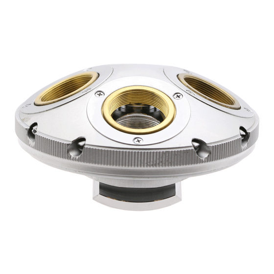
Table of Figures
Figure 1 - A typical JIS screw .................................................................................................................................................. 4
Figure 2 - The BH-NRE modular revolving nosepiece ............................................................................................................. 5
Figure 3 - Basic components of the BH-NRE .......................................................................................................................... 5
Figure 4 - Remove screws securing the cover in place .......................................................................................................... 6
Figure 5 - Remove the protective cover ................................................................................................................................. 6
Figure 6 - The turret assembly (without cover) ..................................................................................................................... 6
Figure 7 - Remove four screws securing the dovetail slide .................................................................................................... 6
Figure 8 - Remove the loose dovetail slide ............................................................................................................................ 6
Figure 9 - Remove the screws securing the detent stop ........................................................................................................ 7
Figure 10 - Remove the mechanical detent stop ................................................................................................................... 7
Figure 11 - Screwdriver modified to remove slotted lock ring .............................................................................................. 7
Figure 12 - Insert screwdriver into bores to lock turret ......................................................................................................... 7
Figure 13 - Loosen the slotted lock ring ................................................................................................................................. 8
Figure 14 - Remove the slotted lock ring ............................................................................................................................... 8
Figure 15 - Remove the pivot-adjustment screw ................................................................................................................... 8
Figure 16 - Remove the center-pivot bearing ball ................................................................................................................. 8
Figure 17 - Components of the turret assembly .................................................................................................................... 8
Figure 18 - Loosen the threaded retaining ring ..................................................................................................................... 9
Figure 19 - Remove the threaded retaining ring .................................................................................................................... 9
Figure 20 - Remove the perimeter bearing balls.................................................................................................................... 9
Figure 21 - Lift and remove the stationary base .................................................................................................................... 9
Figure 22 - All parts cleaned and ready for reassembly ......................................................................................................... 9
Figure 23 - Apply ring of fresh grease to stationary base .................................................................................................... 10
Figure 24 - Reinstall stationary base into revolving turret ................................................................................................... 10
Figure 25 - Place the bearing balls into the ring of grease ................................................................................................... 10
Figure 26 - Engage the threaded retaining ring ................................................................................................................... 10
Figure 27 - Tighten the threaded retaining ring ................................................................................................................... 10
Figure 28 - Thoroughly remove any grease squeeze-out ..................................................................................................... 11
Figure 29 - Apply grease to the center-pivot bore ............................................................................................................... 11
Figure 30 - Place bearing ball into the center-pivot bore .................................................................................................... 11
Figure 31 - Apply grease to the top of the bearing ball ....................................................................................................... 11
Figure 32 - Reinstall the pivot-adjustment screw ................................................................................................................ 11
Figure 33 - Reinstall the slotted lock ring ............................................................................................................................. 12
Figure 34 - Tighten the slotted lock ring .............................................................................................................................. 12
Figure 35 - Place the mechanical detent stop in position .................................................................................................... 12
Figure 36 - Secure the detent stop with two screws ........................................................................................................... 12
Figure 37 - Position dovetail slide onto stationary base ...................................................................................................... 13
Figure 38 - Secure dovetail slide onto stationary base ........................................................................................................ 13
Figure 39 - Apply grease to the four detent notches ........................................................................................................... 13
Figure 40 - Place cover in position on the turret assembly .................................................................................................. 13
Figure 41 - Secure protective cover using three screws ...................................................................................................... 13
Figure 42 - BH-NRE ready to be put back into service ......................................................................................................... 14
Figure 43 - Revolving turret with severely worn mechanical detents .................................................................................. 16
Figure 44 - Close-up view of a worn mechanical detent notch ............................................................................................ 16
Complete Teardown, Cleaning, and Reassembly of the Olympus BH-NRE Modular Revolving Nosepiece
Page 3 of 17
Revision 3