CRU DataPort DP20 Snelstarthandleiding - Pagina 2
Blader online of download pdf Snelstarthandleiding voor {categorie_naam} CRU DataPort DP20. CRU DataPort DP20 4 pagina's.

2
DataPort DP20 Quick Start Guide
1 General Information
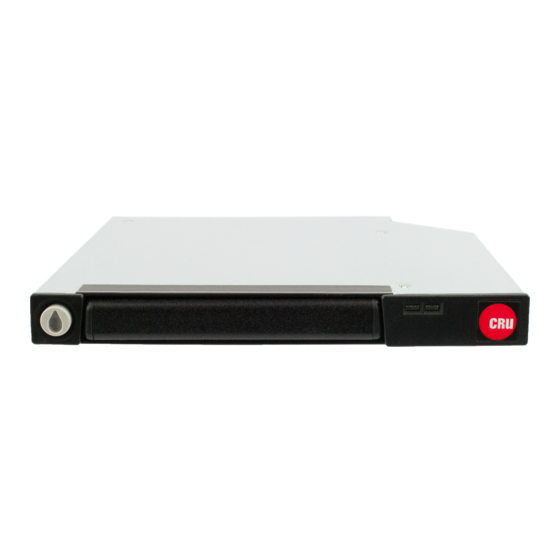
1.1 Identifying Parts
Keylock/
Carrier
Eject Button
1.2 LED Behavior
LED
Drive Power
Drive Activity
2 Installation Steps
2.1 Frame Installation
a.
Mount the DP20 frame into the computer chassis. The DP20 frame is interchangeable with
12.7mm slimline optical drives as well as a variety of slimline mounting brackets and bezels.
Please consult your chassis manufacturer's user manual for specific mounting instructions.
b.
Connect the DP20 frame to the motherboard with a SATA data cable. Then connect it to power
with the computer's 6-pin SATA slimline connector (sold separately).
2.2 Drive Installation
a.
Carrier side caps are packaged within the carrier and are marked "left" and "right" as viewed from
the logo end of the carrier. The "back" mark indicates the end of the rear of the drive should go.
Using two of the supplied screws, mount one side cap to a 2.5" SATA drive. Slide the 2.5" SATA
drive into the DP20 carrier, ensuring that the pins of the unified SATA power and data connector
on the rear of the drive are visible through the slot on the rear of the carrier.
b.
Attach the other black plastic side cap to the HDD, capturing the outer carrier metal and securing
both the side cap and the drive to the carrier.
Do not over-tighten the screws on the side caps, or the carrier may fail to eject properly
from the frame.
Front
Status Lights
Color
State
Green
Solid
Amber
Blinking
The drive inside the DP20 is powered on.
The drive inside the DP20 is being accessed by your
computer.
Rear
SATA Power and
Data Connectors
Description
