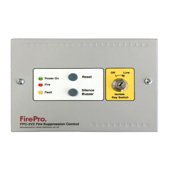
FirePro FPC-2 Bedienings- en onderhoudshandleiding - Pagina 5
Blader online of download pdf Bedienings- en onderhoudshandleiding voor {categorie_naam} FirePro FPC-2. FirePro FPC-2 7 pagina's. Fire control panel system isolation
Ook voor FirePro FPC-2: Bedienings- en installatiehandleiding (14 pagina's), Bedienings- en onderhoudshandleiding (8 pagina's), Snelstarthandleiding (2 pagina's)

Connection of Aerosol Units to Activation circuit
These terminals are for the connection of FirePro®
Aerosol Generators. Test lamps are provided in the
terminals to allow testing of the system before
connecting the FirePro® generators. These test lamps
should be removed from the terminals if a FirePro®
Aerosol Generator is to be fitted.
Any FirePro® generator outputs that are not being
used should be left with test lamps fitted.
Connection to FirePro Units
When constructing leads to the FirePro units the supplied Deutsch Plugs must be used to ensure water-proof
connections are made throughout the installation.
1. Cut cable to required length and strip outer insulation to approximately 50mm.
2. Strip inner insulation to approx. 6mm and using a Deutsch Crimping tool, fix pins to the exposed ends of
the cable, including the earth.
3. Place heat shrink or rubber boot over the end of the cable. Identify correct
socket on plug by the numbers/letter on the side of the plug and push through
the gasket at the bottom of the plug until a click is heard and the pin is locked
in place.
4. Place the locking wedge inside the plug to ensure pins remain secure. (Male
plugs the locking wedge is orange. Female plugs the locking wedge is green)
5. Using the heat shrink and rubber boot, seal the back of the plug.
Indications
Power Indicator
Operates as long as voltage is coming into panel – range is 6-30vDC.
Fault Indicator
Operates whenever any circuit fault is detected in the system. It is a common indictor for
both the activation and detection circuits.
Fire Indicator
Operates when the detection circuit goes into alarm.
Fault relay
The Fault Relay is normally energised and will de-energise upon any fault condition on the detection part or the
extinguishant part of the control panel including total loss of power. Volt free changeover contact that will
operate whenever there is a fault condition. This contact is rated for a maximum of 30V DC and
1Amp. These ratings must not be exceeded
Fire relay
The Fire Relay will energise upon activation of a fire condition. The relay will remain activated until the control
panel is reset. Volt free changeover contact that will operate whenever the system is triggered to alarm. This
contact is rated for a maximum of 30V DC and 1Amp. These ratings must not be exceeded.
fp_c2_m5.3
Page 5 of 7
