Alderon Industries Vizzyalarm VZW-02 Bedienings-, onderhouds- en installatiehandleiding - Pagina 4
Blader online of download pdf Bedienings-, onderhouds- en installatiehandleiding voor {categorie_naam} Alderon Industries Vizzyalarm VZW-02. Alderon Industries Vizzyalarm VZW-02 6 pagina's.

Vizzyalarm™ 1-Zone WiFi Alarm Panel - Installation Instructions
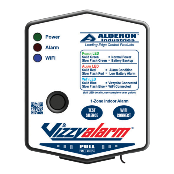
Installation of the Alarm Panel
6. Plug the alarm panel power supply into a standard wall outlet or
receptacle (120VAC, 50/60 Hz), and then plug the quick connect
of the power supply cord into the incoming power receptacle of
the alarm panel. The green power LED should illuminate (solid)
when powered (Fig. 11).
Testing the Alarm Panel
1a. Test the alarm panel by pressing and holding the test/silence
pushbutton (Fig. 12). If properly installed, all of the LEDs should
illuminate (quick flash) and then after approximately 5-6 seconds,
the buzzer should annunciate (quick pulse). Immediately release
the test/silence pushbutton after the buzzer annunciates a quick
pulse tone to end the test. After the test/silence pushbutton is
released, the alarm panel will auto reset for the next alarm cycle.
Test product weekly to ensure system integrity.
CAUTION: Holding the test/silence pushbutton for longer than 5-6 seconds
along with the buzzer quick pulse tone will change the low battery alarm
enable or disable setting (approximately 9-10 seconds; total elapsed time).
See complete user guide for settings information and step 1c below to test
auxiliary contacts separately.
1b. Test the alarm panel by activating the sensor (signaling device)
(Fig. 13). The alarm LED should illuminate (solid), buzzer should
annunciate (solid), and auxiliary contacts should activate. Press
the test/silence pushbutton and the buzzer should silence while
the alarm LED remains on (solid) with activated auxiliary contacts
(alarm LED slow flash). After the sensor is deactivated, the alarm
panel will auto reset for the next alarm cycle. Test product weekly
to ensure system integrity.
Note: If multiple sensors are used, perform a test for each sensor connected
to the alarm panel to ensure complete system operation.
1c. Test the auxiliary contacts by pressing and holding the test/silence
pushbutton immediately followed by pressing and holding the
WiFi/connect pushbutton (Fig. 14). The auxiliary contacts
connected to the AUX inputs on the terminal block should activate
(alarm LED slow flash). When the WiFi/connect pushbutton is
released, the auxiliary contacts connected to the AUX inputs on
the terminal block should deactivate.
Note: Once the test/silence pushbutton is released, it will exit the auxiliary
contacts testing mode.
Page 4 | Installation Instructions
Alderon Industries, LLC - Leading Edge Control Products | 218.483.3034 | [email protected] | [email protected] | alderonind.com
(continued)
(Fig. 11)
5 ft. Max
(Fig. 12)
(Fig. 13)
(Fig. 14)
AUX
Building Automation System (BAS)
Another High Water Alarm
Any Monitoring System
